<HOME
<Workshop Stuff
<Proxxon Mini Drill and Stuff
AC Foot Switch for Small Power Tools
And some safety improvements to the PFS-135A foot switch
|
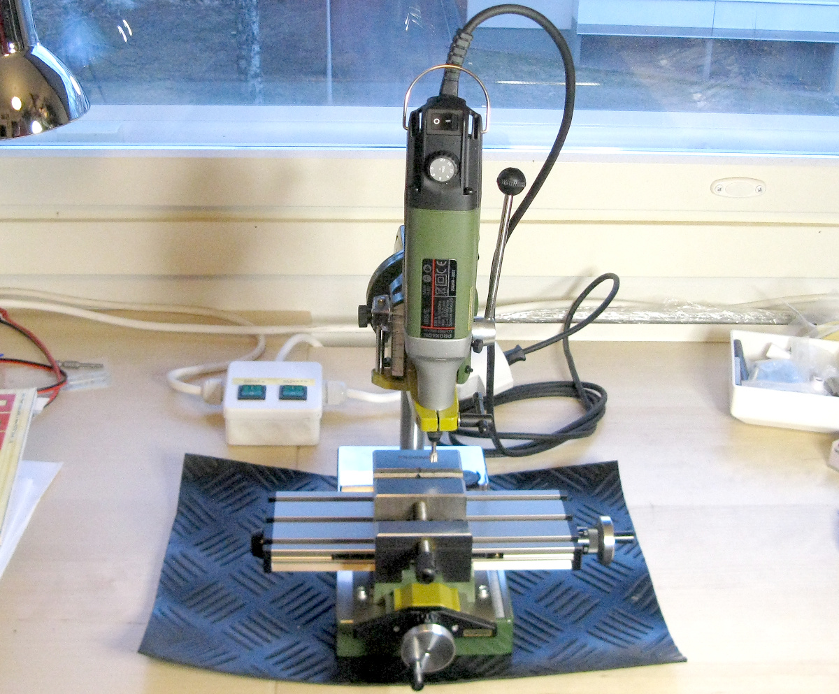
I wanted a foot switch to use with my Dremel tool. My current
Dremel tool is a
Proxxon
IBS/E—the word is pretty much genericized by now,
don't you think? I also have the MB-200 drill stand
(which I modified for improved depth
setting) and KT-70 compound table,
a USB microscope for accurate drilling
of PCBs, and other stuff.
See this page for the whole story.
These are all pretty much
toys compared to the milling machines I've once had access to, but
these are cheap, they will fit on my desk, and they are convenient to have
immediately on hand for the occasional small job.
And despite being small hobby tools, these are all actually pretty well
made. When used for jobs appropriate for their size, I'm quite happy
with them. But I digress. I wanted a foot switch for this thing.
Proxxon does make a suitable foot switch, their
No. 28 700
Footswitch FS, at a very reasonable price, but I saw one major
drawback in it. It has a long inlet power cord, but a very short outlet
cord. I think the idea is that the drill's power cord is long enough to
reach down to the floor where the foot switch is—and it is
long enough for that. But in order to bypass the foot switch for continuous
operation, I would have to crawl under my desk to unplug the drill from
the foot switch. I wanted a dedicated switch right there on my desk
to bypass the foot switch! Therefore... DIY.
|

|
The PFS-135A foot switch and electrical safety
|
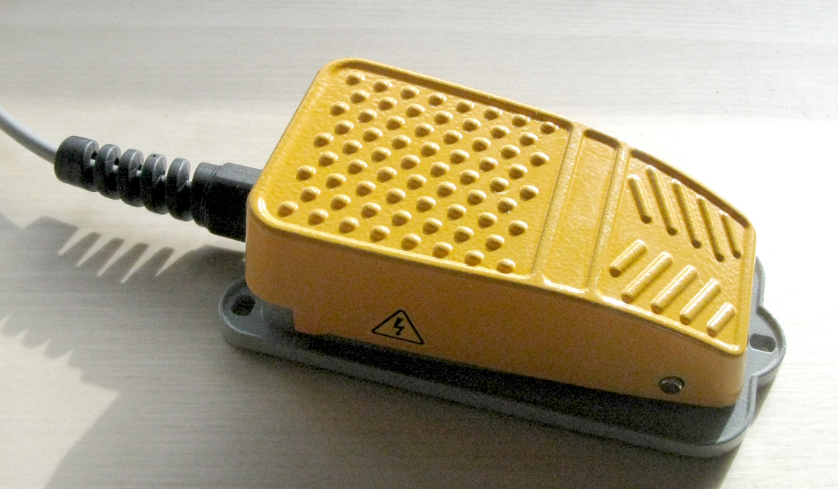
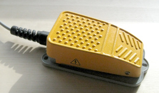
First, I needed the mechanical foot switch / pedal itself. There's plenty of
cheap plasticky foot switches / pedals available, but I soon found the
PFS-135A, which is totally hardcore. It has an all-metal
construction, and it looks pretty serious as well! (And it was immediately
available locally, which also helped choosing.)
It's pretty generic and no-name, available from many electronics suppliers,
and quite cheap. Most reviews I saw on the Net rated it very highly.
It is specified for 250 VAC and 10 A, and it has an SPDT microswitch
and a 1.8 m cord with three wires, connected to the common, normally
open and normally closed terminals of the switch.
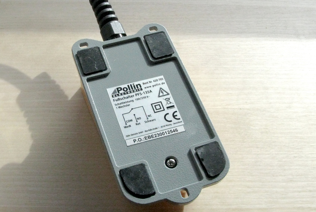
There is no safety ground wire to this metal-chassis device, which is why
some reviews on the Net claim it is a death machine, and only
suitable for switching low voltages, e.g. for controlling a relay.
|
|
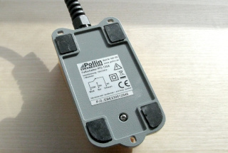
So of course I wanted to see what's inside the device. To open it, you first
must loosen the single screw on the
bottom of the chassis
a couple of complete turns (or you can just remove it completely).
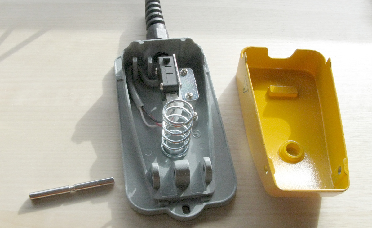
Next, you slide out the bar that forms the pedal's hinge at the end away
from the cord. Pressing down on the pedal slightly, right at the hinge,
first push one end of the bar inwards with a small screw driver, then
grab the other end with pliers and pull it out. The bar has a groove in its
center position, which may get stuck on the edge of the pedal—just
wiggle it onwards while varying how much you press down on the pedal.
Once the bar is out, the pedal will come
apart cleanly, with no tiny parts flying out uncontrollably (only one pretty
large spring, which is easy enough to find if it does jump out).
|
|
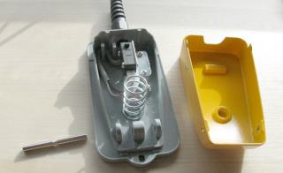
Here's the internal structure of the device. The bar you pulled out (far
left in the photo) has
a groove in its center, which is where the single screw goes to keep
it in place. There's a hefty spring, not really attached
to anything, but kept in place by protrusions in the bottom and top halves
of the pedal when they're assembled. It's the only loose object you'll find
inside on disassembly.
The cord enters the pedal through a feedthrough, which grips the cord and
also has a flex part protruding outward. In addition, the cord goes around
a strain relief structure inside the pedal, so it's doubly certain not to
get yanked out too easily. Very good design in my opinion, and so far, quite
safe!
|

|
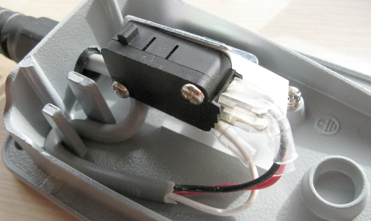
The cord is rated at 300 V and is 20 AWG each wire, which means
0.5 mm2 in people language. The connections to the switch
are appropriately insulated with shrink tubing, and there's an extra plastic
flap between them and the metal chassis. However, the rather thin conductors
are soldered to the spade type connectors of the switch. This is not
bad in itself, but the wires are soldered simply to one surface of
the spade, so if the solder were to melt in some overcurrent condition, the
live wire would immediately become loose inside the metal chassis, and could
very well electrocute someone! A soldered wire carrying household
AC should always go through a hole, and then turn back and wrap
around itself, so even if the solder were to melt, the wire would still
be held in place.
I think this does constitute something of a risk in an ungrounded,
metal chassis! There is a single screw terminal for a safety ground
connection, but it is not connected to any wire.
|

|
So while the device's construction is mechanically very good, I did want to
improve its electrical safety a bit. Since I was going to use this device
as a simple, momentary OFF/(ON) SPST switch, I would only need two terminals
of the SPDT switch, and could thus use one wire in a 3-wire cord for safety
ground (4-wire AC cables do exist, but aren't too readily available). I
replaced the
original cord with a length of thicker 1.5 mm2 3-conductor
cable, which came from a grounded extension cord I dismantled for other
parts (see below). The safety ground conductor of this cable is the standard
yellow/green, as it should be. This thicker cable would just
not fit through the original flex strain relief,
so I cut away all its useful bits and used it simply as a plastic grommet (to
line the threaded hole in the pedal's metal chassis). This provides no strain
relief whatsoever, but especially with this new, thick cable, I do absolutely
trust the strain relief inside the pedal to hold it in place!
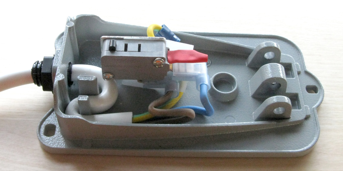
I crimped insulated connectors to all three conductors, and connected the
yellow/green to the safety ground point, and the blue and the brown to the
switch. I used a fresh, new microswitch, as I happened to have those
immediately available in shelf in the correct form factor. It's a
250 V 16 A Honeywell-branded switch, whereas the original was
unbranded and likely "cheap Chinese". It did look and feel
quite decent, though. I insulated the unused terminal ("normally
closed") with heat shrink tubing for good measure. Then I simply
re-assembled the pedal.
|
Note, by the way, the switches are typically marked
with two maximum loads, e.g.
"16 (3) A". The
first number 16 A is for purely resistive loads only! For a
motor load, the second, much smaller, value (3) A applies!
A motor load differs from an inductive load in its large inrush current
at start-up. Finally, there's a lamp load whose current spec is
even lower than the motor load's! That's for incandescent lamps,
which can have an absurdly tremendous inrush current before their
filaments heat up! Look up the datasheet. They're often quite interesting,
and they'll tell you all you want to know.
You should find resistive, lamp, inductive and motor loads all specified
separately, and a bunch of other useful information.
Of course, a motor load refers to an actual motor being directly fed
by the household AC, not to
a switch-mode power supply feeding a motor, as is the case in your
typical Dremel tool, regardless of brand. You might do well to follow the
lamp load specifications instead!
The switch box for foot switch bypassing etc.
|
With the foot switch on the floor, I wanted a separate switch box on my desk
within easy reach, for two purposes:
- For bypassing the foot switch, when I wanted to run the drill
continuously. There are times when I don't want to keep my foot on the pedal
all the time. And I'd rather avoid the hassle of unplugging the drill from
its foot switch thing (especially if that meant having to crawl under my
desk and hurting my back) and plugging it directly into an outlet instead.
- For isolating the foot switch, so the drill (or whatever else is
hooked up) doesn't get
powered on unintentionally if I step on the switch by accident! Sure, every
hand-held drill has its own power switch, which will do just that. But I'm
trying to provide for other applications that I may not have thought of yet.
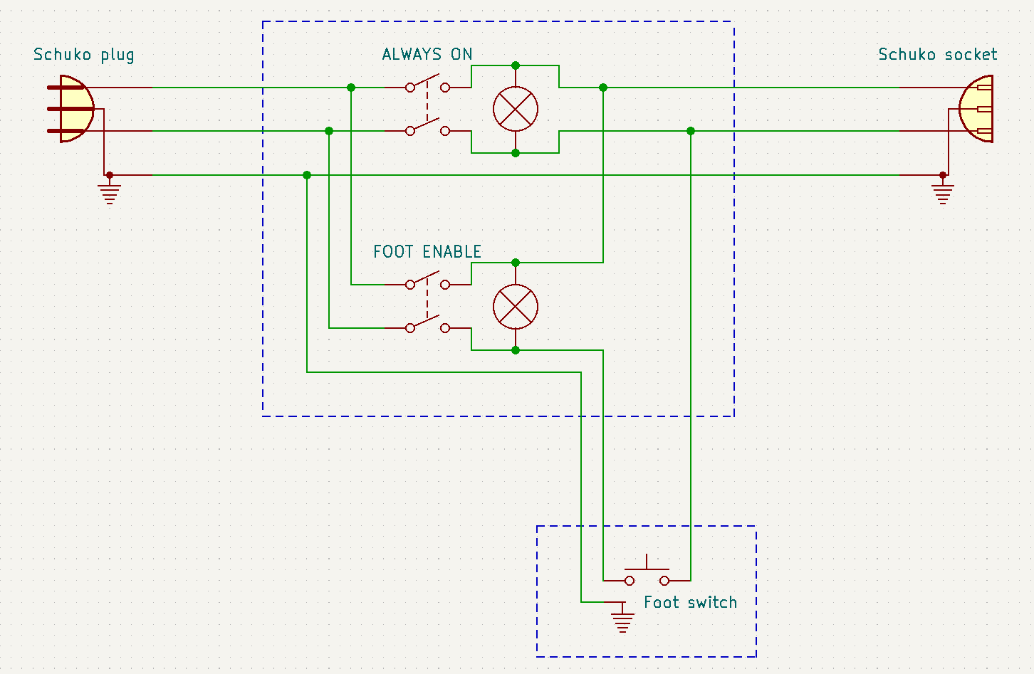
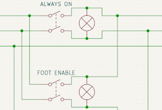
The circuit is simplicity itself, using a Schuko plug and socket
(scavenged from a grounded extension cord) as AC input and output, and two
illuminated DPST rocker switches. See the
full schematic to get the
complete picture.
|

|
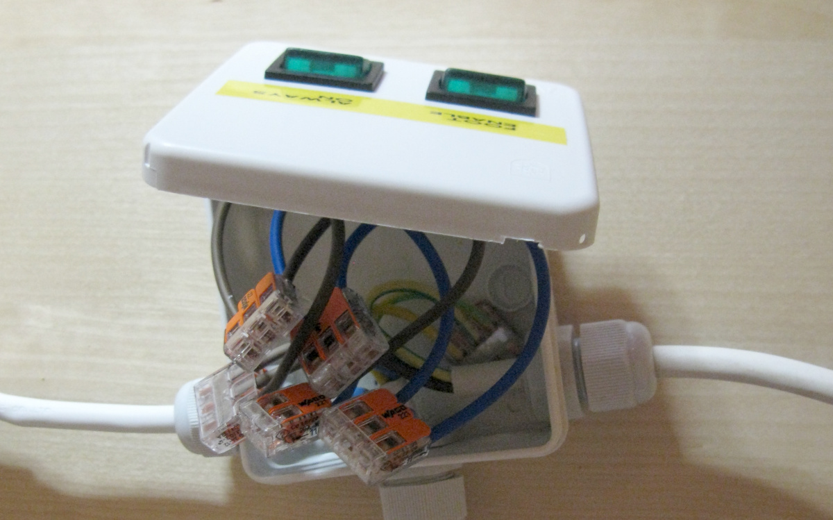
I constructed the thing in a small electrical junction box (not even a
project box) which I fitted with three feedthroughs including strain relief.
The rocker switches had the same kind of spade connectors as the microswitch,
so I crimped a bunch of wire pigtails with mating connectors. To tie things
together, I used 3-contact lever-type
splicing connectors by
Wago. These are so much more convenient than screw-type
terminal blocks a.k.a. "sugar cubes"! And I especially love
Wago's transparent connectors, as I can be certain that the stripped wire is
where it should be, and that the wire insulation continues inside the
connector by a safe margin.
It's an absolute mess with the lid open...
Before closing the lid, I tested all parts of the circuit for continuity and
shorts with every position combination of every switch. Then I hazarded a
live test with my Dremel tool, and observed that everything works as intended.
|

|
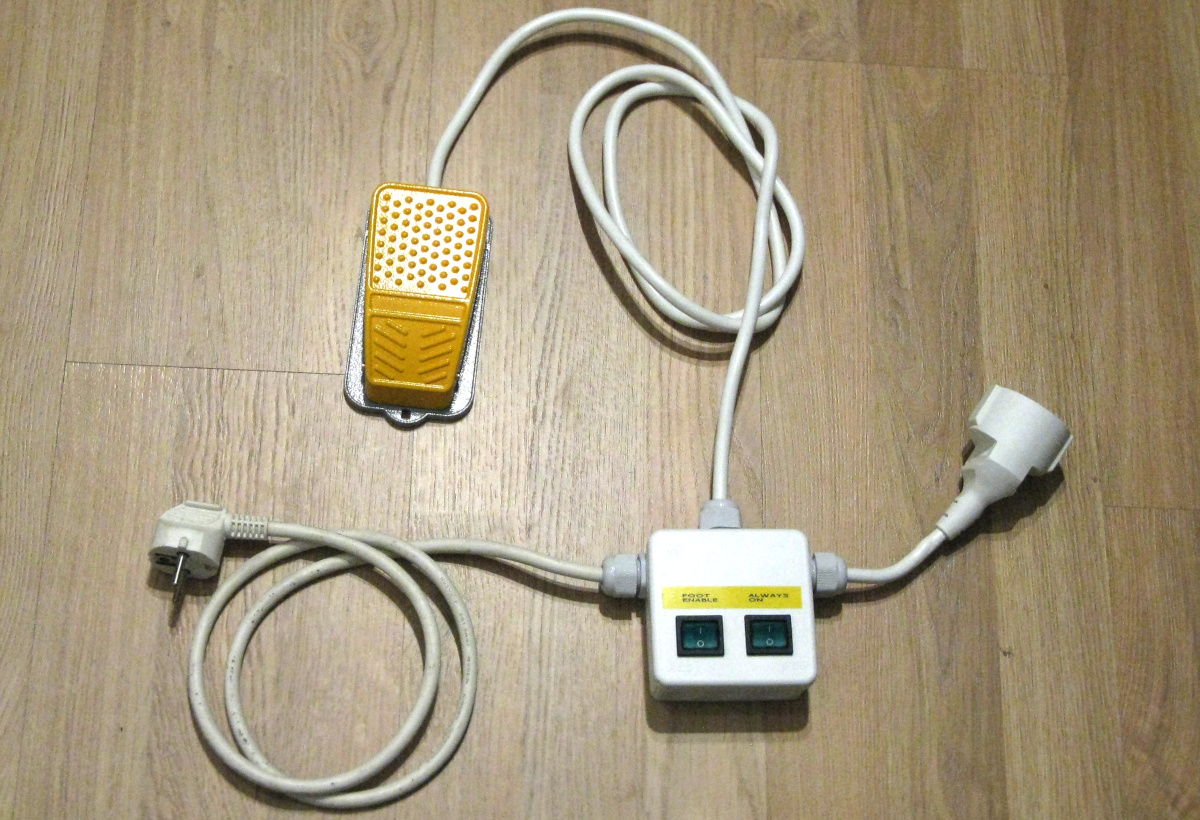
With the lid closed, it's no worse than any of my other homebrew stuff.
The cord on the left plugs into a multiple outlet extension cord on my desk.
The cord on the right provides a socket into which I plug my Dremel tool, or
whatever other tool. (Note that this cord is short, just like in the Proxxon
foot switch. The difference is, this short cord sits right there on my desk,
rather than on the floor underneath my desk.) The foot switch at the end of
the cord towards the top goes around the back of my desk, and down to the
floor. With the box sitting on my desk, the two switches for powering
up the drill or for enabling the foot switch are always within easy reach.
Perfect!
I chose switches with built-in indicator lights, so either switch, when
activated, lights up green. Also, when the "Foot enable" switch
is on, pressing the foot switch causes the "Always on" switch to
light up, which kind of makes sense, and is almost like a design choice.
However, when the "Always on" switch is on, pressing the foot
switch (which does not actually do anything) causes the "Foot
enable" switch to light up, which is somewhat nonsensical. Oh well.
Slightly more annoying is that when one switch is on, the other one is
also dimly lit, just noticeable under ordinary room lighting. I think this
must be due to capacitive coupling between the wires in the footswitch
lead! Again, oh well.
|
This foot switch can be used with grounded devices, whereas
the Porxxon Footswitch FS is ungrounded and has those flat
"Europlug" connectors. However, Proxxon's choice of
"Europlugs" automatically limits the power rating of the
device that can physically be connected to it. My choice of grounded Schuko
plug and socket does not! I'm almost tempted to substitute an
ungrounded "Europlug" for the output just to be sure nobody else
can do anything stupid with it either. So keep in mind the switch ratings,
and obey them! A 3 A max motor load on the microswitch
means about 700 W max (on European 230 V household AC), which is
plenty for a small Dremel tool, or even the average Black and Decker hobby
drill, but not necessarily for a serious hand drill, like the bigger
rotary hammers
by Hilti! (But with a 16 A max resistive
load, you could control a 3500 W waffle iron with it just fine!) Any
bigger motors you'll want to control using an appropriately
rated relay or contactor. But feel free to control that contactor with this
foot switch thing—or to include the contactor inside the same box.
A serious word of warning!
This apparently simple project deals with household AC voltages. Do
NOT attempt anything like this if you are at all unsure
of what you are doing! That includes selection of properly rated switches,
connectors, wires, enclosures, everything! That includes the construction
and assembly techniques and tools at all stages of the project! That includes
thorough testing of all possible failure modes and assembly mistakes!
At best, you will blow a fuse if you get the tiniest detail wrong. At worst,
you will blow up your mini drill, set fire to your house, and kill yourself
and your cat, all in a split second as you plug your contraption in!
Best not to try this yourself, and if you do, don't blame me for
anything bad that happens!
And, once more, do obey the current ratings of your switches!!!
Depending on the switch, a 1 kW waffle iron may be ok, but a 1 kW
hand drill may not be!!! Unsure why that's so? Stop right now!!!
Do you need to google "A and V to kW"?
Stop right now!!! Don't know the difference between resistive
and inductive? Stop right now!!! Need to ponder,
whether you can replace the broken 12V 800mA power supply for your WiFi
router with the 12V 1500mA one you have on hand? Stop right
now!!! (The correct answer is yes, you probably can. But
how many examples can you think of, where you can't? Unless you come up
with at least two, stop right now!!!)
Antti J. Niskanen <uuki@iki.fi>