After being introduced to the art of carbon fiber composite materials (originally with model rocketry in mind), I began seriously contemplating an ultralight telescope made out of carbon fiber. Say a 300 mm f/4.5 might just be compact enough to transport whole, maybe. Searching the Net for any possible information on carbon fiber telescopes, I just happened to stumble upon the concept of a string Dobsonian and realized that I had struck gold: lightweight, compact, yet near-instantaneous set-up. As if that's not good enough, the greatly simplified collimation mechanism is an added bonus!
|
Huh? A string telescope? Consider a standard truss-Dobsonian. A minimalist would use only three (not four) trusses. The structure is absolutely rigid. Now replace the six stiff poles that make up the trusses ...with strings! Sounds crazy, but a truss structure made of strings is rigid—as long as the strings are in tension. So now you use two or three stiff, spring-loaded poles to keep the strings tensioned. The benefits? First, you only need two or three poles instead of six, so your structure is lighter. Second, collimation can be accomplished by adjusting the strings, so you don't need any other collimation mechanisms for the optics. Third, and most importantly, setting up the scope involves just pressing the spring-loaded poles into place and you're done in just a minute or two, with no tools required! |
Mind you, I would be very, very wary of the string telescope concept if it were my own invention, but the concept seemed sound, and a quick search on the Net found many such designs. (Interestingly, I never did find much info on carbon fiber in amateur telescope making.) So, when I also found a good deal on 400 mm optics at Telescope Service in Germany, a project was born: An ultralight, ultracompact 400 mm Dobsonian utilizing string trusses and carbon fiber construction. (When inquiring on Pollux's IRC-channel about strings with minimal stretch, the whole project still seemed too crazy to publicize. Therefore I told them I was building a space elevator. I still refer to the scope by that name.)
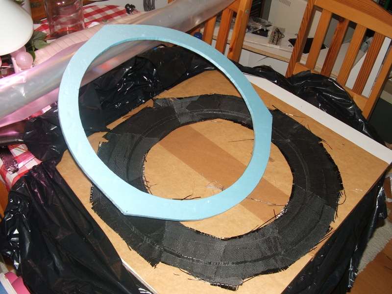
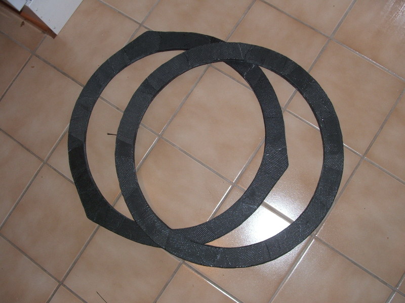
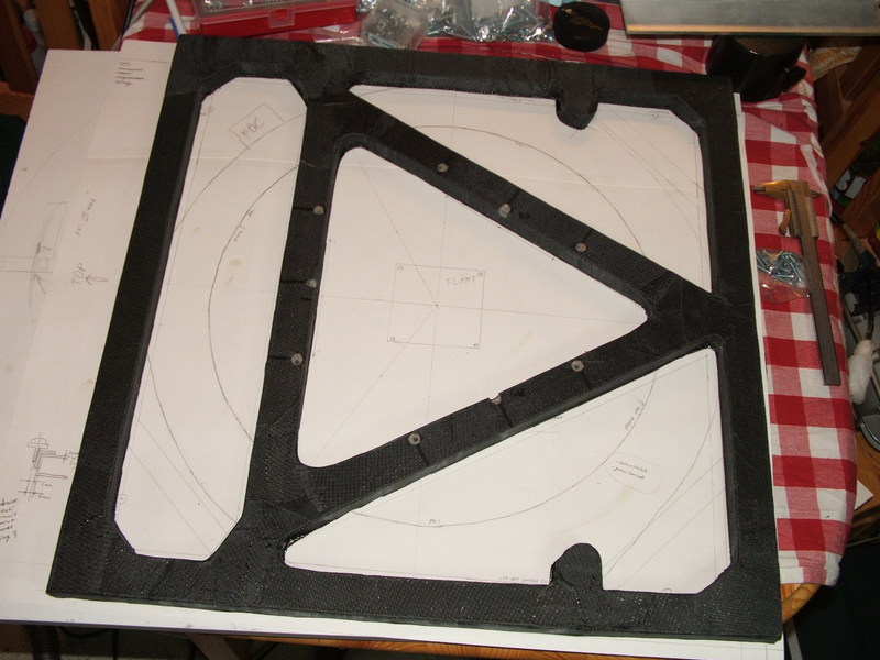
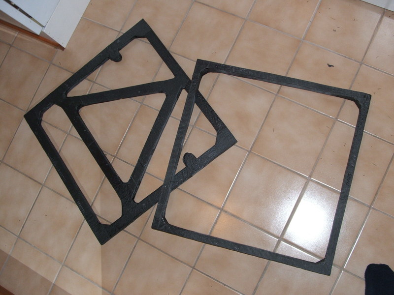
The core is laminated with carbon fiber fabric (285 g/m2 satin weave with SP-115 epoxy) by standard vacuum bagging technique. The epoxy is mixed in disposable cups and applied to the carbon fiber fabric with a paint brush (don't even try to clean it after use, it's disposable as well). From personal experience, this method is fine for satin weave fabric, but avoid twill weave: its fibers bunch up when you try to brush on the epoxy, and it just goes all horrible. Once the epoxy has cured, the excess material is trimmed away. These are the top and bottom rings for the upper tube assembly:
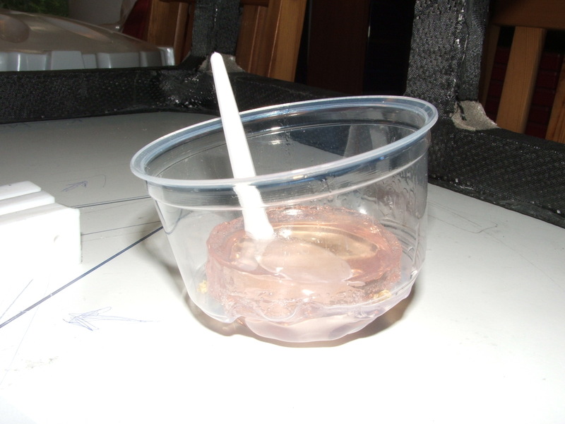
If you mix a larger amount of epoxy but don't use it all, watch out for thermal runaway after it begins to gel. A sufficiently large quantity can reportedly catch fire. About 40 grams of the stuff was enough to melt the plastic cup:
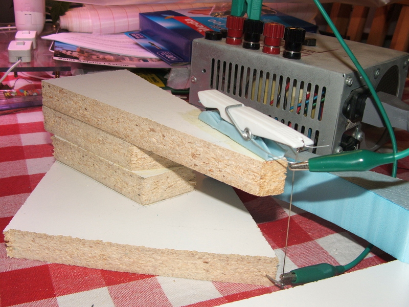
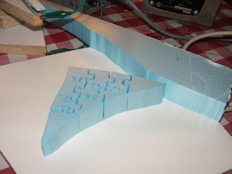
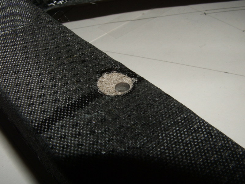
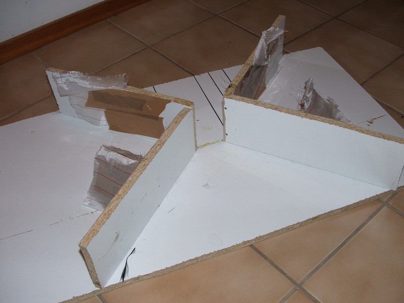
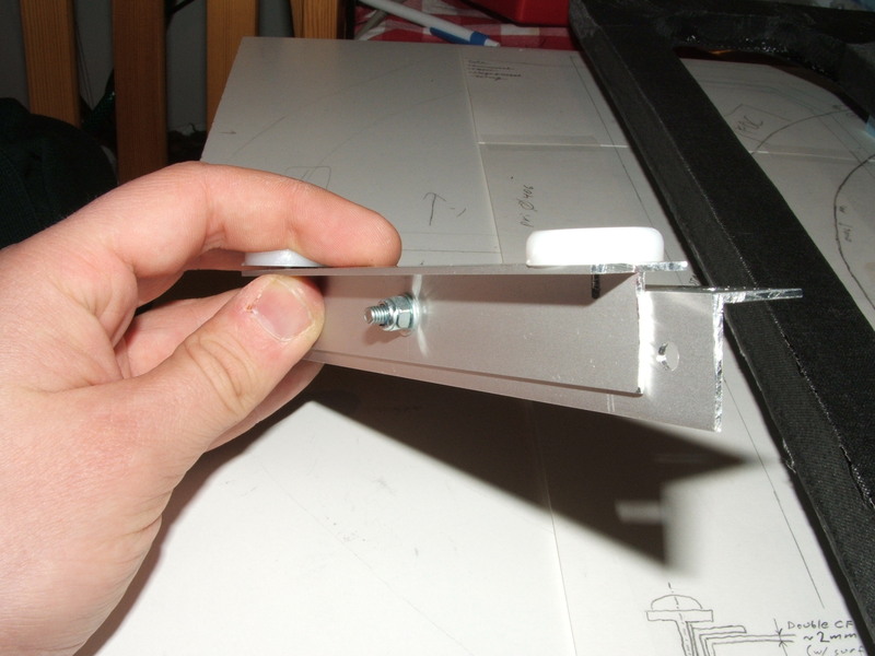
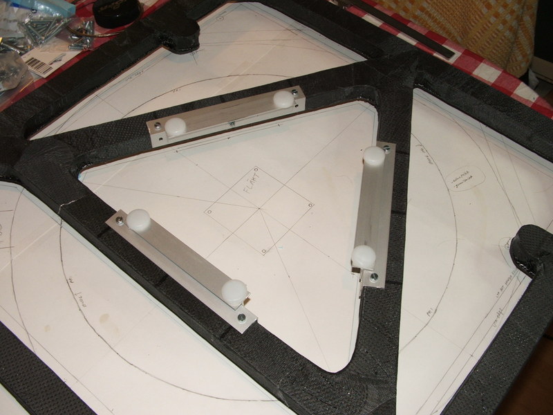
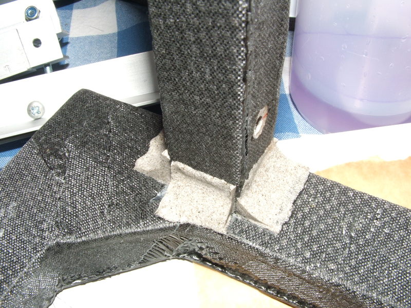
The laminated structures withstand relatively little pressure perpendicular to the surface. Bolts through the laminate, when tightened, would squash the carbon fiber surface layer into the foam core. Therefore, wherever bolts are to be attached, hardpoints must be made by drilling a hole, hollowing out the foam core, and casting a mixture of epoxy and filler material (I used microspheres). The hole for the bolt is then drilled through the hardpoint. These are the points where the primary mirror's flotation system will be attached in the lower tube assembly:
The carbon fiber surface is left rough by the laminating process (due to the nylon release-fabric). This would be great for inside surfaces of the scope, but unfortunately specks of dust emanate from the surface, so once the parts have been epoxied together, the completed units are coated with epoxy. The now shiny surfaces with the fabric structure showing through look cool, but the insides of the scope must be spray-painted flat black.
|
Making carbon fiber structures at home You will need:
|

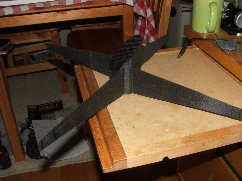
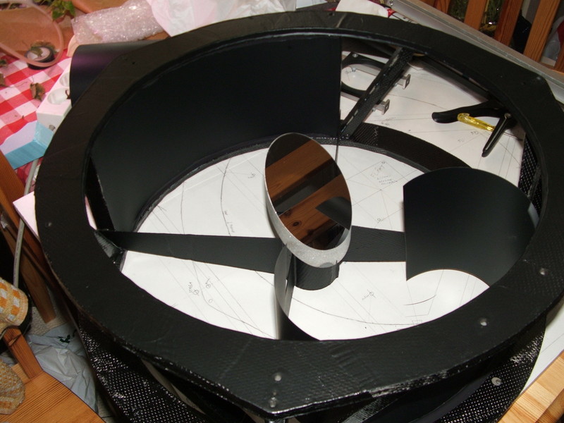
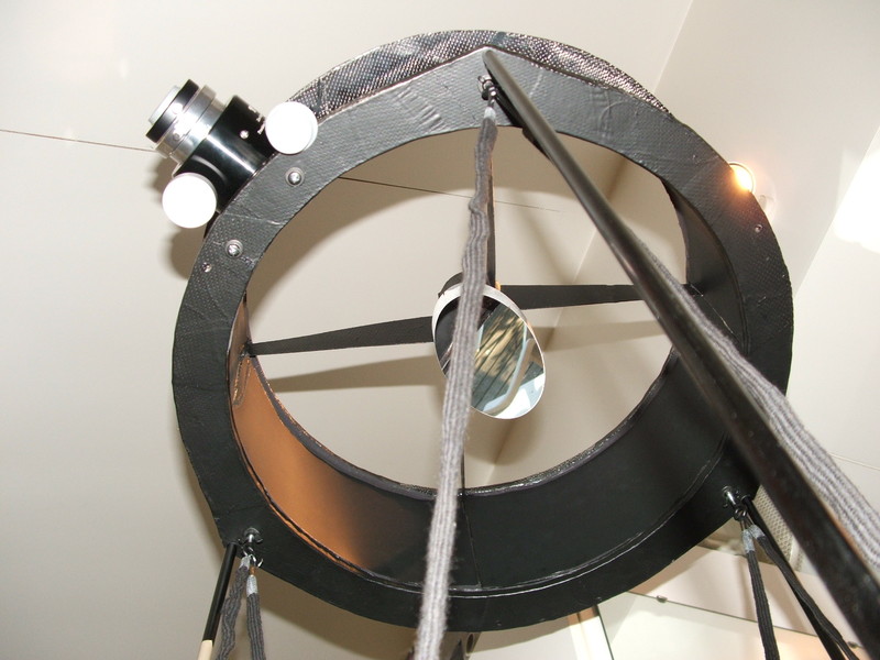
The secondary holder is attached to the spider with no collimation mechanism, and the entire assembly is glued directly to the UTA cage, again with no collimation mechanism:
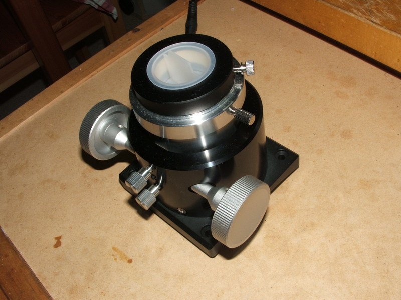
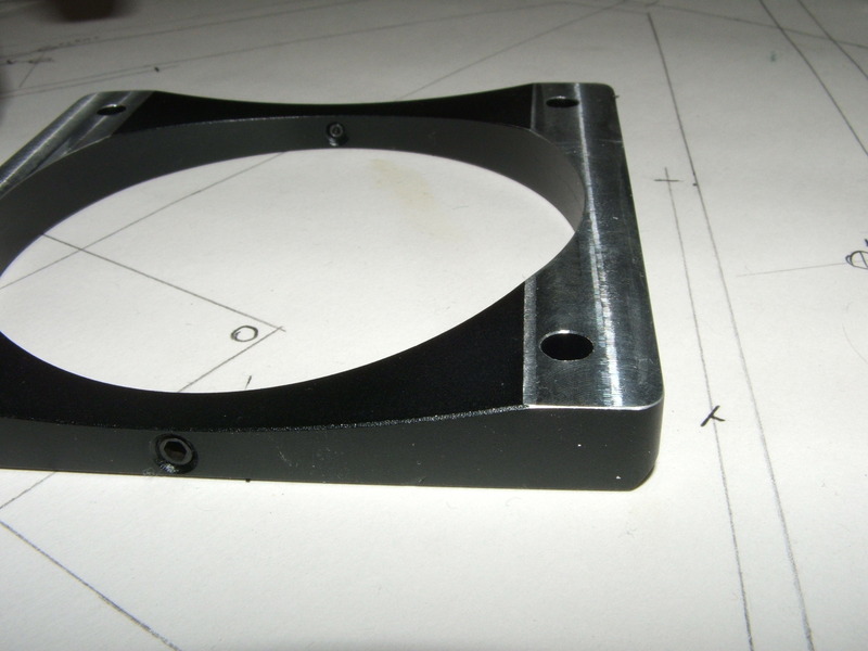
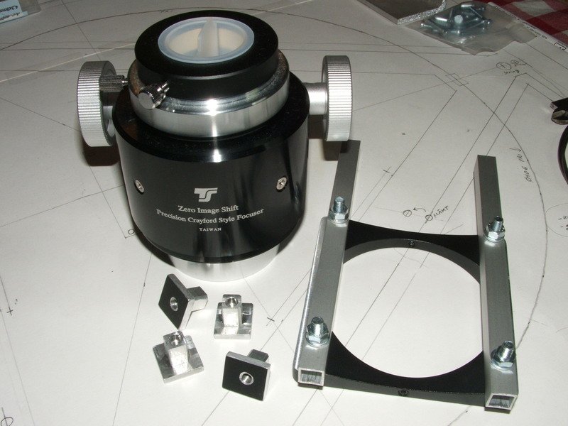
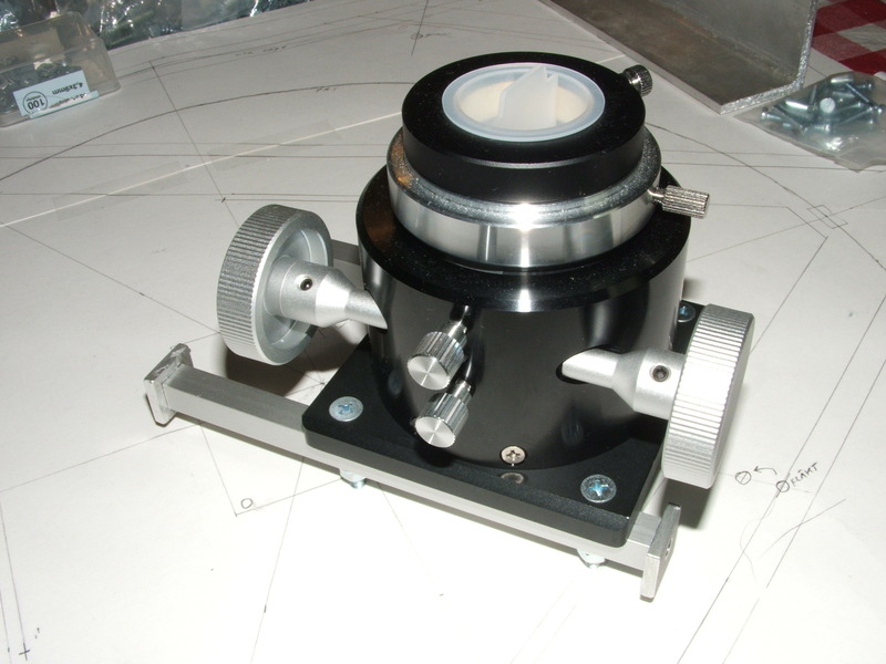
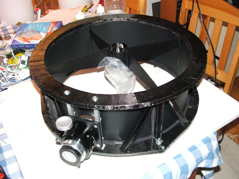
The focuser is a Crayford type also from Telescope Service. Why does the base of all focusers have to be curved??? The curvature of your telescope's tube never, ever fits the curvature of the focuser base anyway! I machined off a slice to fit it squarely onto two pieces of square aluminum tubing. I then machined end-caps with threaded holes, which I glued onto the tubes so the whole thing could be bolted onto the UTA. The focuser's orientation is adjusted by placing pieces of aluminum foil (from a maksalaatikko, no less) between the base and the tubing.
Another minor modification I made was to replace the plastic block, which presses the focuser's axle against the eyepiece drawtube, with a PTFE one that I machined myself. The original block was some kind of extruded thermoplastic, perhaps polycarbonate. The axle had noticeable static friction against this plastic, especially when the pressure of the axle against the drawtube was increased. This resulted in highly jerky motion, which would have been a nuisance when trying to fine-focus. The new PTFE block has almost no static friction even at high pressure, and the focuser's overall feel is improved immensely! Such a small detail, but it makes a world of difference.
The secondary was glued to its holder with four blobs of silicone sealant. The UTA was enclosed with thin black PVC sheet, attached to the UTA with contact cement and black silicone sealant:
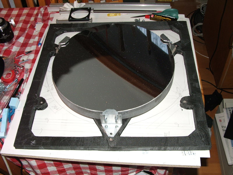
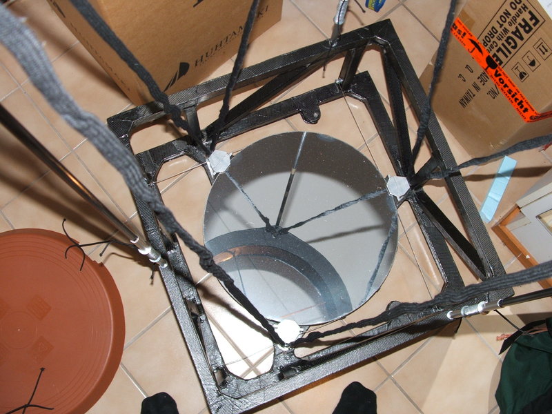
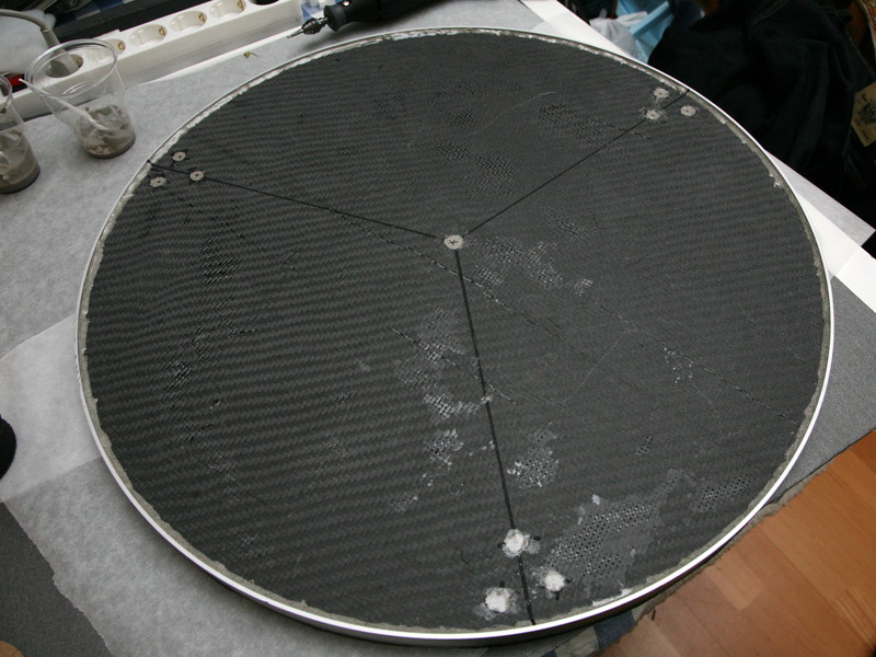
Lateral support for the mirror is provided by a two-part sling of steel cable (like this beautiful three part sling without the spring-loaded upside-down U-sling). The sling is held in position with small rubber pads glued onto the mirror's edge with contact cement. The three claws around the mirror keep it from falling out in transport or if the sling should for some reason come loose, but normally they do not touch the mirror at all. (No, the mirror isn't really as dirty as it looks in the photo.)
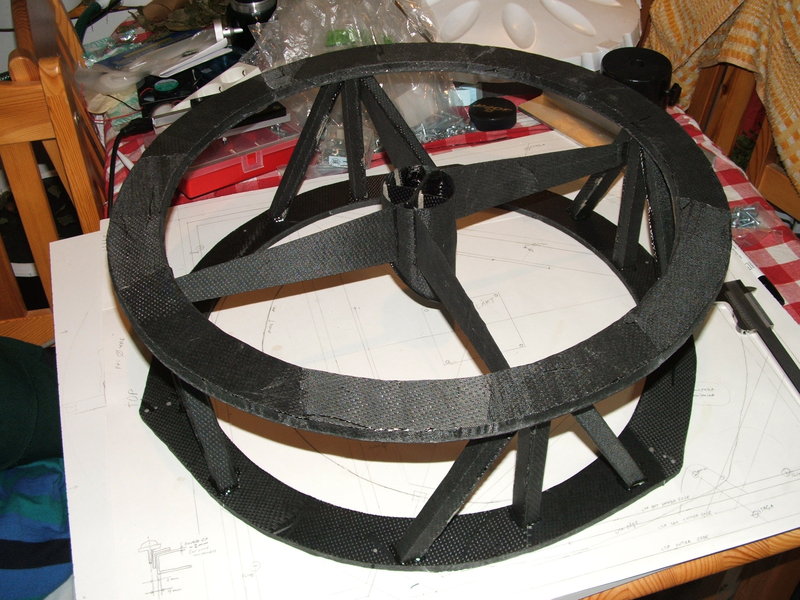
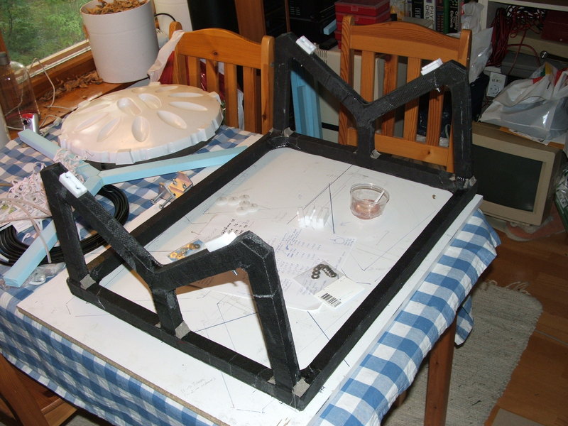
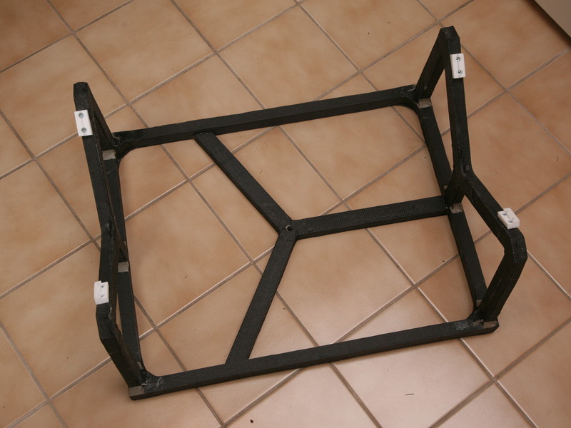
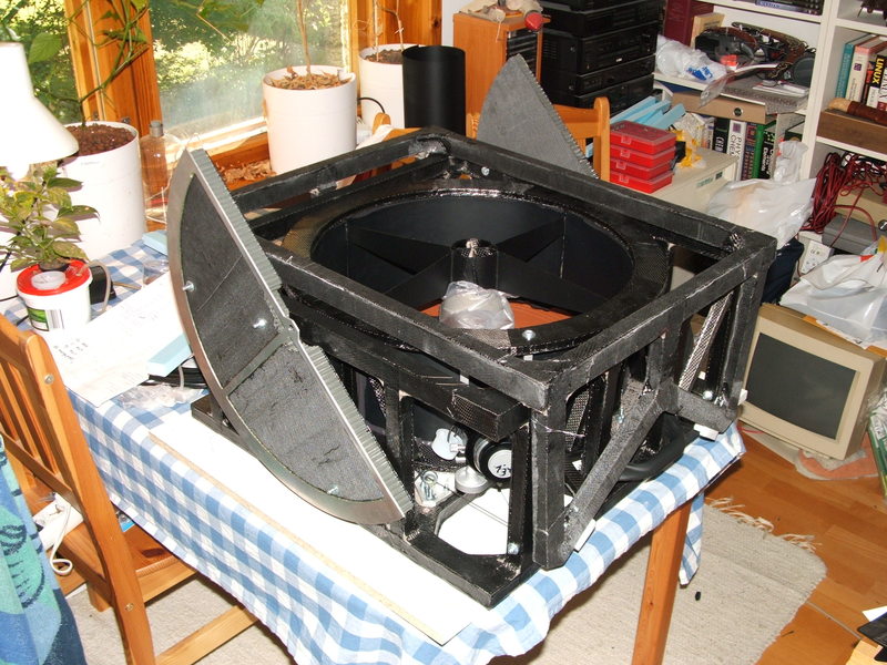
The primary weighs 12.7 kg, so the LTA structures are for the most part laminated twice for extra strength. The vertical segments of the LTA structure were joined to the upper and lower frames with epoxy, fillets were made of epoxy/microsphere mixture, and the most critical joints were further reinforced with carbon fiber.


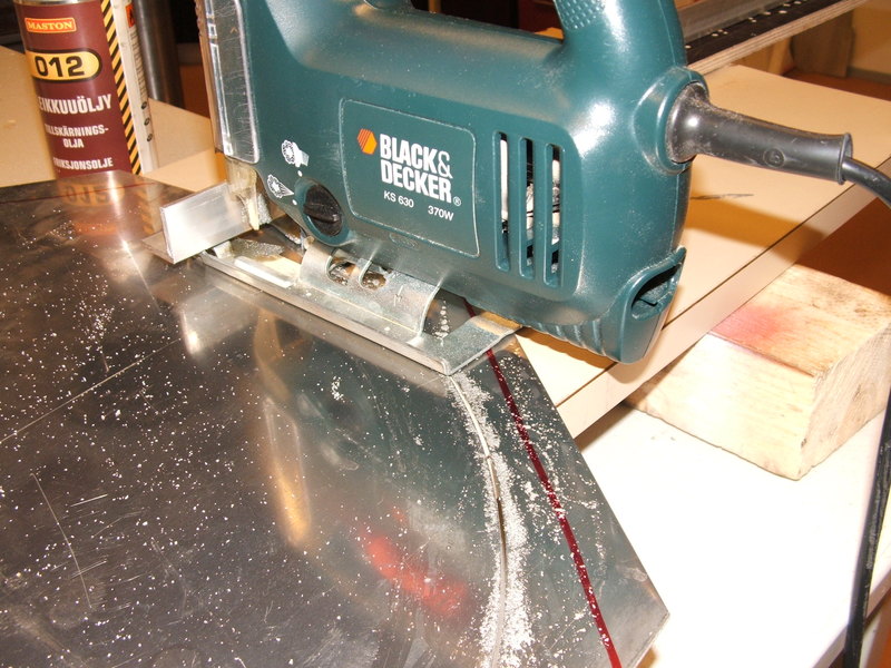
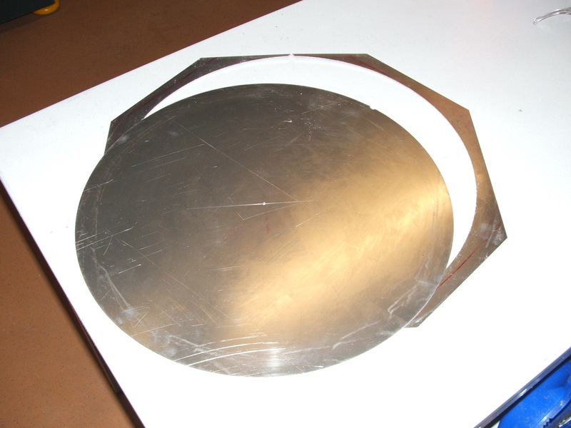
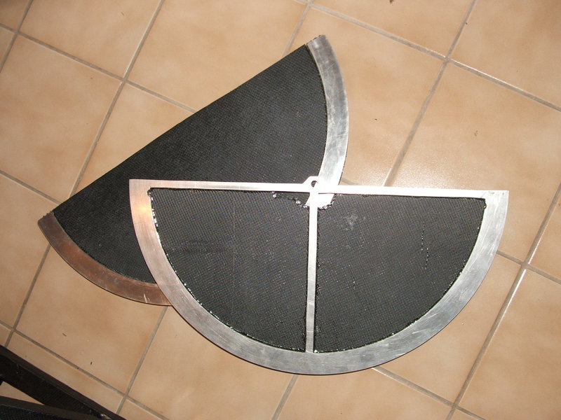
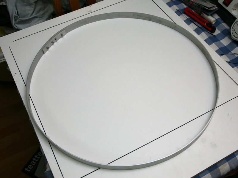
An aluminum rim was cut with a jigsaw, to become the weight-bearing surface of the altitude bearings. The saw was statically mounted on a beam of metal profile, and the 2 mm thick aluminum sheet, bolted at the center, was fed into the saw blade to create the circular bearing surface. The precision achieved by such a simple method is rather astonishing. Only a quick touch of sandpaper was needed to finish the surface.
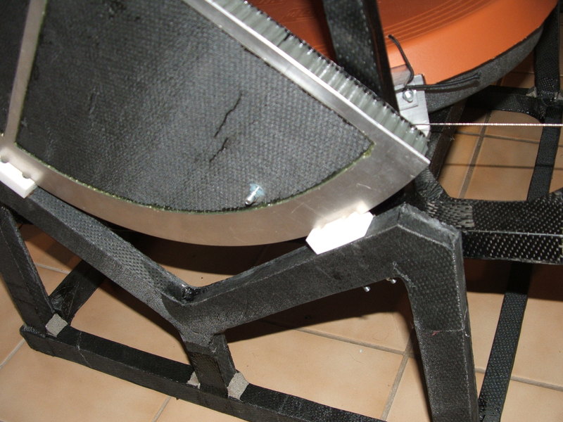
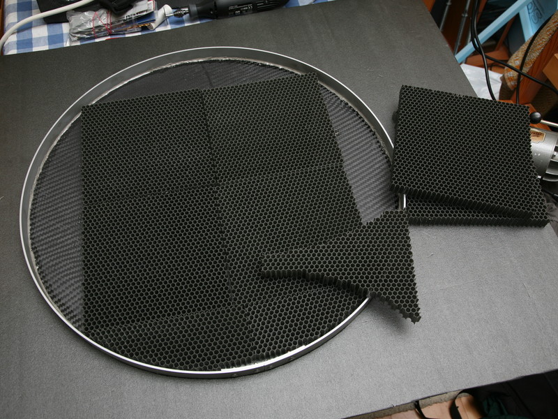
The altitude bearings are of course carbon fiber laminate, but instead of foam, the core is plastic honeycomb material. Sheets of carbon fiber were impregnated with epoxy and cured, then epoxied to either side of the honeycomb. Hardpoints were made for attachment to the LTA. The weight-bearing aluminum rim was epoxied onto the bearing's edge. One of the bearings also has a place for an angular encoder, for future use when I computerize the scope.


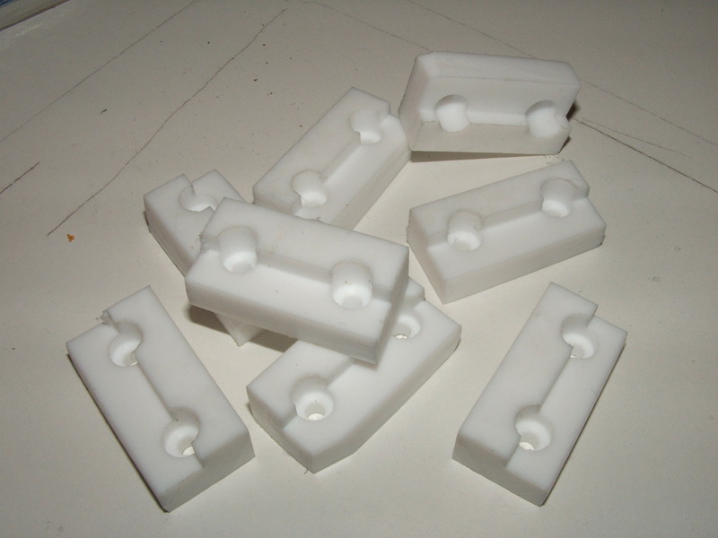
Of course, I didn't get the strings' lengths just right, and the collimation screws ran out of adjustment range. To get the collimation into the right ballpark, I made small plastic thingies around which to wrap excess Fireline. Of the 8 strands of Fireline per string, only a single strand is wrapped onto each thingy. This way a single wrap consumes about 20 mm of Fireline, shortening the truss by about 2.5 mm. Also, any slightest flexing induced by the thingies is also divided by 8, and therefore kept to its absolute minimum. The thingies are small enough to hide inside the shoelaces. I installed them at the upper end of the string trusses, so they also help keep the shoelaces from sliding down!

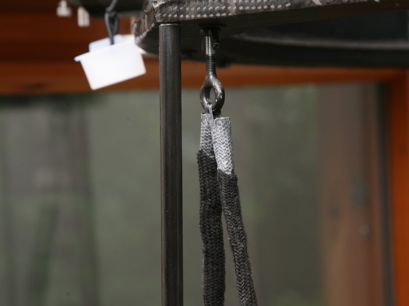
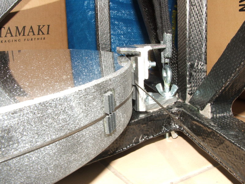
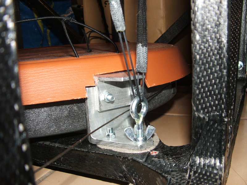
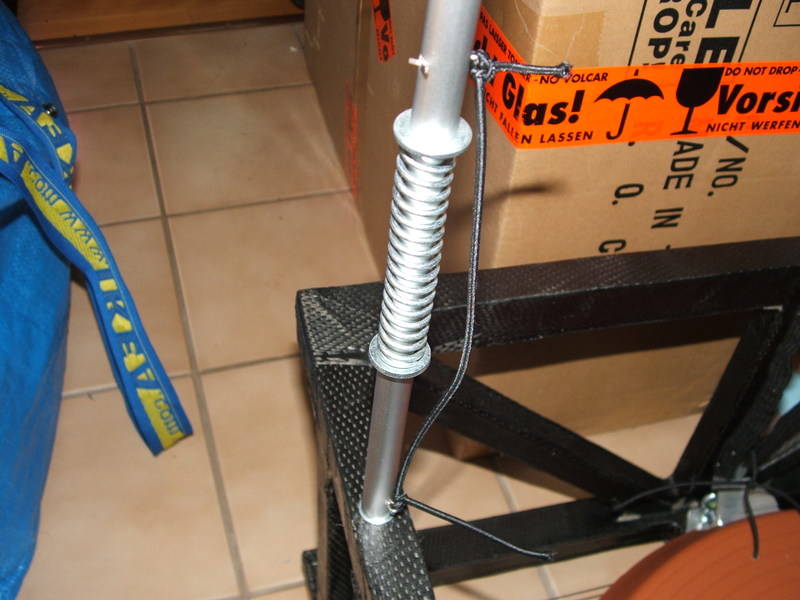
Tension is maintained with spring-loaded carbon fiber tubes of 10 mm diameter, which are pinned to studs (small screws) on the UTA and LTA. These tubes flex and wobble quite a bit, but since they are not actual structural parts (they just maintain tension on the strings, which are the structural parts here), that does not matter. Instead, they are very easy to install and remove with no tools required: just press them into place, and the tension keeps them there. The springs come from old umbrellas (the type that open up at the press of a button). I used those also in my old 200 mm, in the spring-loaded bolts of the primary cell. Always salvage the big, hefty spring before throwing a broken umbrella away! They are hard to find elsewhere, and are most useful in all kinds of projects!
The scope is covered by a shroud, which is black on one side, and an ugly silver-gray on the other. Unfortunately the ugly side has to go on the outside. The shroud is supported by the truss strings and spring-loaded poles, and additional support is provided by three elastic bands tensioned between the UTA and LTA.
- kuva gummibandit - kuva shroud@scope
The axle which connects the rocker box to the ground board is hollow, for easy future attachment of the azimuth encoder. Too bad the altitude encoder couldn't be integrated into the rocker box also.
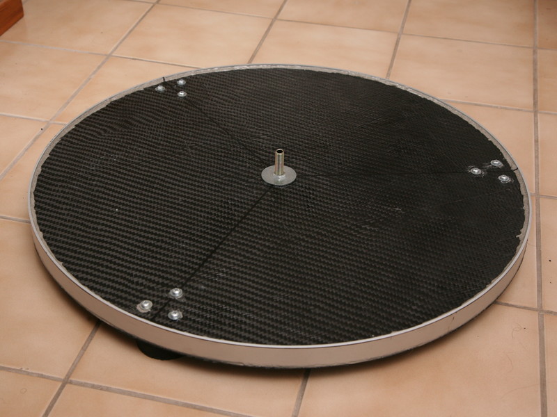
Like the altitude bearings, the groundboard is also a sandwich of two carbon fiber sheets with honeycomb material in between. It is lined by an aluminum rim, along which the six PTFE blocks on the bottom of the rocker box ride. The rim is made from a length of 25 x 2.5 mm aluminum stock (the carbon fiber and honeycomb composite is 20 mm thick, so the rim protrudes 5 mm beyond its surface), bent into shape and riveted together. Obviously the seam must be as smooth as possible. The rim is glued onto the carbon fiber, with fillets added for increased strength. The honeycomb and second layer of fiber are then added, and finally hardpoints are made for the axle bolt and feet.

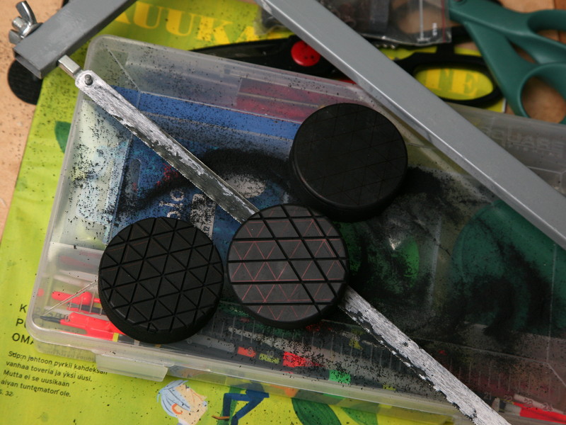
The ground board sits on three junior-sized hockey pucks. I have used those as feet on all my Dobsonians, and several other projects as well.
- rb@gb - scope@rb@gb

(paremmat kuvat t�h�n)
The whole thing, mount included, weighs about 21 kg (45 pounds). Here's a breakdown of the weight:
| Optics etc. | Primary | 12.7 kg | Total 13.7 kg |
| Secondary | 0.4 kg | ||
| Focuser | 0.6 kg | ||
| Structural parts | UTA | 0.8 kg | Total 7.6 kg |
| Trusses + fabric etc. | 0.6 kg | ||
| LTA | 3.6 kg | ||
| Rocker box + ground board | 2.6 kg | ||
| Grand total: | 21.3 kg | ||
If only I had a thinner primary, the scope would be even lighter, way below 20 kg (at the cost of a more complicated primary support, of course) but I had to make do with what was available. But just for comparison, here's some examples of Dobsonians you can get commercially. Perhaps 21 kg for a 16-incher isn't all too bad after all?
|
Meade Starfinder 16" Meade Lightbridge 16" Starmaster 16" Discovery Telescopes 15" Orion Skyquest *12"* Celestron Starhopper *12"* Obsession 15" My carbon-fiber 16" |
77 kg 58 kg 53 kg 44 kg 37 kg 36 kg 27 kg *21 kg* |
All of this is still in the very early stages of planning, however. But I've already started collecting necessary hardware:
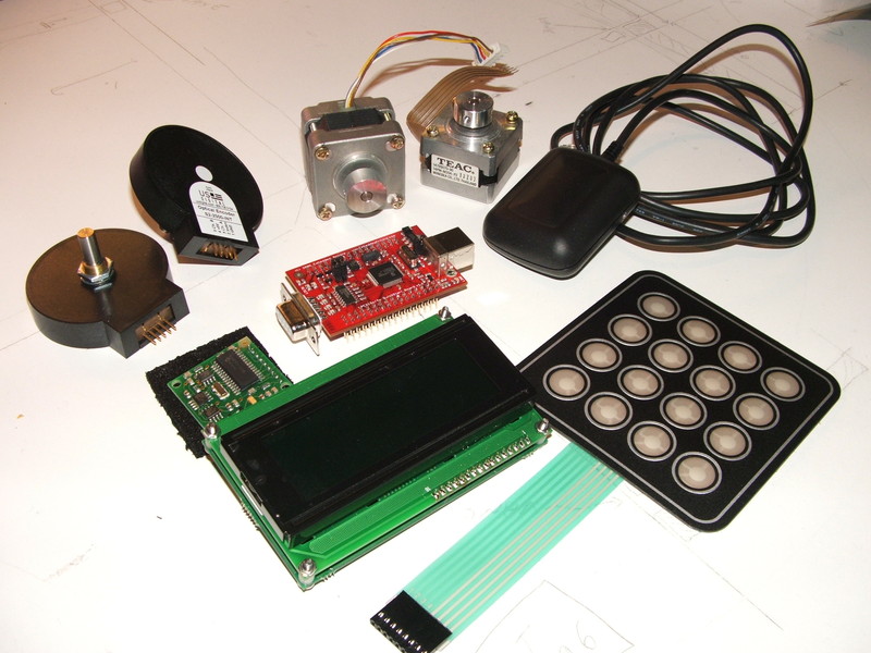
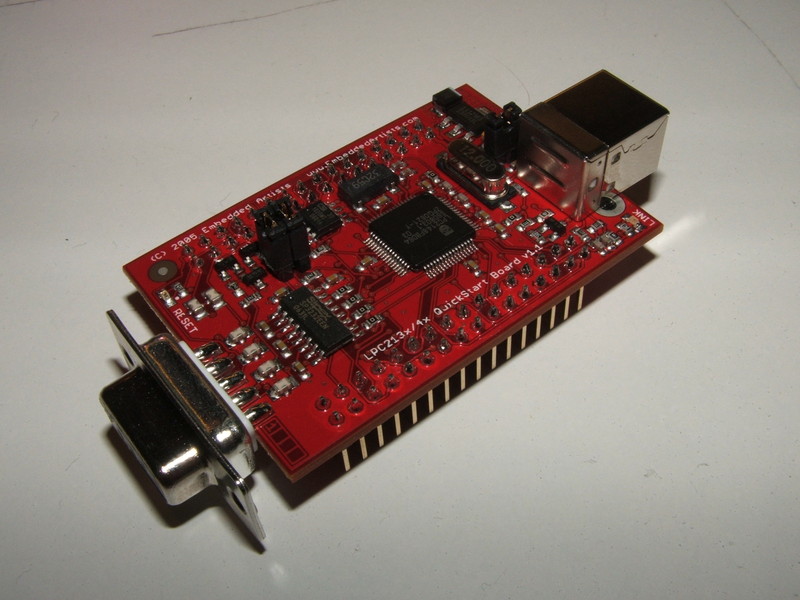
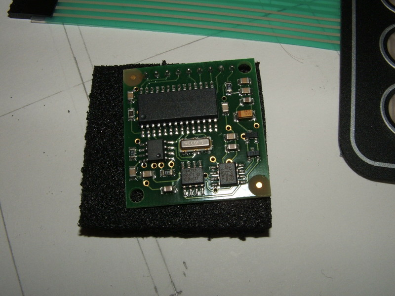
The computer is a QuickStart Board from Embedded Artists featuring the Philips/NXP LPC-2148 microcontroller chip. It has a 60 MHz ARM7TDMI core, half a megabyte of flash program memory, 32 kilobytes of RAM, 2 kilobytes of E2PROM, a real-time clock, SPI, I2C, serial and USB buses, plenty of general-purpose I/O-pins and much more, and it's about the size of a credit card. Perfect for this application, and it has enough processing capacity to run a small nuclear power plant. It can be programmed with GCC (you need the ARM version, of course) and the program is uploaded over the serial channel.
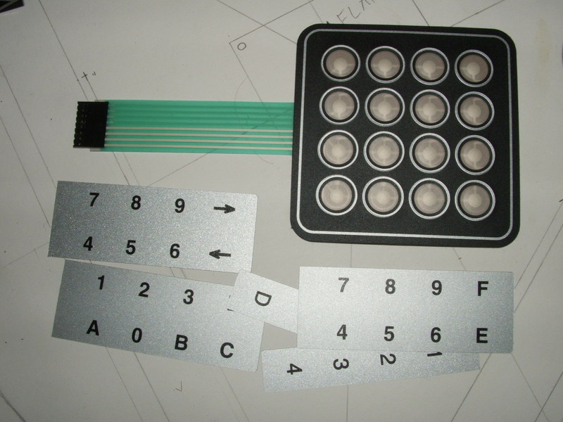
The user interface is an LK204-25-R-E LCD-module from Matrix Orbital. It has a 20 x 4 character LCD with red letters on a black background, a backlight that is adjustable to very dim levels when necessary, and a serial interface. In addition it has a controller for a 5 x 5 key keyboard and 6 general-purpose output pins, all driven over the same serial interface. Perfect. I also chose the extended-temperature option, as the Finnish winter can be quite cold. The keypad I chose is a 4200-series 4 x 4-key membrane keypad from In2tec: tactile switches, adhesive mounting and insertable legends. The GPIO-pins on the LCD-module will drive a piezo beeper and backlighting for the keypad.

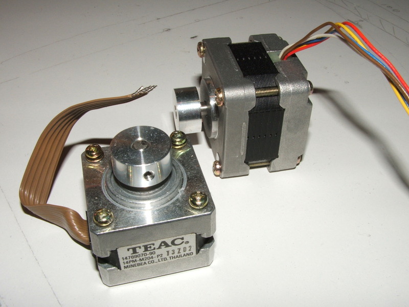
The scope will be driven by small 1.8 degrees/step stepper motors from old floppy-disk drives, operated in microstep mode by PWM. The PTFE bearings of the Dobsonian mount will be replaced by ball bearings and the motor axles themselves. The aluminum altitude bearings and azimuth ring are thus driven directly by the motor axles, providing a backlash-free friction drive with about 1:100 reduction. Microstepping is still necessary with that reduction, unfortunately.
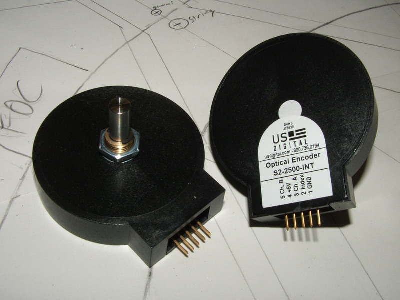
The position of the scope will be sensed by two S2-2500-INT incremental encoders (10,000 steps per revolution) from US Digital. To make programming the ARM computer a bit easier (less real-time stuff to deal with), I might outsource interfacing to the steppers and the encoders to a pair of PIC16F690 microcontrollers.
Future enhancements may include GPS automatic setup: coordinates and time received from GPS and electronic compass and inclinometer to enable automatic pointing of the telescope to suitable stars for alignment, requiring the user only to center the star in the field of view. But first I have to get all the basic stuff working.
The string concept, weird as it initially seems, is sound. While the structure may not be exactly as rigid as a traditional truss structure made of heavy-duty tubing, it is more than sufficient for visual use, and brings with it enormous benefits: the scope saw its First Light on Pollux's star gazing trip in the Autumn of 2008. I carried the entire scope, alone, several hundred meters from the parking lot to our observing site, over some quite sub-optimal terrain. Just minutes after arrival, it was already set up and I was searching for the Veil Nebula. That did raise some eyebrows. And when in use, there was really no hint of the exotic construction of the instrument: it does not flex or wobble, in fact it feels just like my old conventional 200 mm truss Dobsonian—only bigger.
Collimation works as advertised: If you consider the strings to be a rigid structure, the entire LTA and UTA hang from it at three points each. Adjustment of these is exactly the same as adjusting a standard Newtonian collimation system. Only instead of first moving the secondary to center it in the focuser's view, you adjust the focuser's orientation. This is the least critical adjustment and needs to be done only once.
The strings really need to have as little stretch as possible. Archery bowstrings are widely used by others, I used Fireline fishing line, which seems good also (at least when turned eightfold). The springs need to be quite stiff to support the UTA when pointed near the horizon, especially with my rather heavy focuser and some bigger eyepieces. A TeleVue 27 mm Panoptic, weighing about 500 g, is still within limits. A 31 mm Nagler at ~1 kg would be entirely out of the question. The lower strings must not become flabby at all, otherwise the UTA will sag and you lose collimation. Interestingly, while a faster f/ratio usually makes collimation more critical, here it places less demands on the springs and strings since the base is wider. At f/6 this construction with my heavy UTA might be quite hopeless.
The bottom line? I may just start rebuilding—again!—my old 200 mm scope. It should weigh absolutely nothing by these techniques! The smart thing would have been to rebuild it first, for practice, but I just haven't got the patience... :)
Keywords: atm, amateur telescope making, carbon fiber telescope, carbon fiber dobsonian, string telescope, string dobsonian, ultralight telescope, ultracompact telescope, ultralight dobsonian, ultracompact dobsonian, carbon fiber composite material, microsoft sucks