<HOME
<Test equipment
Setting up GPIB on Raspberry Pi
Using an Agilent/Keysight 82357B USB-GPIB adapter
And SCPI over any other interface, e.g. serial, USB or
Ethernet!
There's also some PyVISA program
examples on how to control GPIB instruments remotely
In older instruments, dating from times way before USB, the de-facto
computer interface has been HPIB (Hewlett-Packard Interface Bus), later
renamed GPIB (General Purpose Interface Bus) or
IEEE-488. Modern
instruments have USB and Ethernet built in, but the obsolete GPIB remains
the bane of those of us wanting to control older instruments by computer.
Since GPIB host adapters for modern PCs are something of a specialty item,
they are not cheap!
|
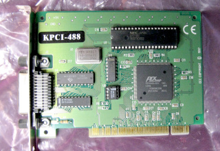
I once found an ISA bus GPIB host adapter in a junk pile at my old
university. Later I even managed to dig out a PCI bus version, a
Keithley KPCI-488, which I used till late, but needed a
dedicated, equally obsolete junk pile PC to use it in! Keeping the PC
in any way up to date would also be problematic, if Linux drops
support for ye olde 32-bit x86. Curse modern PCs that no longer have
either of these legacy buses! (I bet PCIE host adapters do exist, but
do I really want to know how much they cost???)
USB-GPIB host adapters have existed for a good while now, made by all the
big players, but they also have never been cheap. Several DIY designs
have emerged, but many have some kind of limitations, as the GPIB
bus can be hard to drive (no pun intended, honest!) if there are many
instruments connected. Also software support may be questionable.
|
|
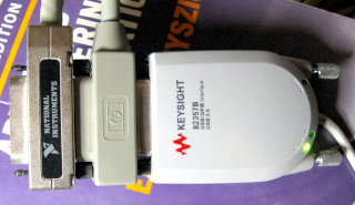
But on eBay, there are sometimes Agilent 82357B adapters (or, later,
the same model Keysight adapters) available at suspiciously low prices. They're
sold in quantity, so they can't all be used ones. They may simply be
counterfeit ones, with basically the same innards as the original
(the Agilent unit has, in fact, been reverse engineered and its
schematic is available on the Internet).
They could also be authentic units rejected in factory quality control, but
smuggled out before being destroyed as they should have been (which would
account for the the number of defective units people have encountered
and sometimes repaired themselves). But
whichever the case, if the device runs the authentic firmware (which is
not stored in the device ROM, but loaded at runtime), driver compatibility
at least should be very good.
|
This is an overview of what I had to do to get GPIB up and running
on a Raspberry Pi, using an eBay 82357B.
It is mainly intended as a checklist for myself, in case I need to do it
again some day. The most relevant resources I used during setup are
this post
on Element14 and this
post on xDevs, plus various other Google hits. Most of the setup
process should probably be extremely similar on any Linux system, not just
the raspberry-flavored ones. I only chose to dedicate an old Raspberry Pi for
interfacing, because who knows what havoc various potential differences,
ground loops, RF etc. might wreak in my lab, possibly killing a
USB port on my desktop PC, or even the entire machine. I can access the
headless Pi over the network, and that's galvanically isolated. Plus I
already had a Raspberry Pi 3 Model B without much active use. (I soon
swapped a Pi 2 Model B in its stead.)
I also present a brief overview of how to get up and running with the
Python GPIB libraries and with PyVISA. This allows you to control
not only instruments on a GPIB bus, but pretty much any instrument that
talks any flavor of SCPI, be it over GPIB, serial port, USB or Ethernet.
There's some simple program examples on a
separate web page.
Installation of ready packages
So I did a fresh install of
Raspberry
Pi OS "Lite" 32-bit (Debian 11 Bullseye) on the Pi 3B. Older
or newer Pies should do just fine as well. (In fact, I subsequently
found a disused Raspberry Pi 2B and swapped the SD card into that,
and it's been running the show ever since, leaving the more powerful 3B for
other, more demanding use. Even a first-generation Pi would probably suffice,
but I'm already using mine as a camera server with an old NoIR Pi camera.)
I don't expect the 64-bit OS to differ in any relevant way either (though
I couldn't have swapped a 64-bit distro into the old 32-bit Pi 2B, so I'm
glad I went 32-bit). Once I had the Pi OS set up, with network
etc. up and running, I tackled the GPIB interface. Many posts I
read started out with installing a specific kernel. I used the stock
kernel (5.15.84 at the time) that came with Raspberry Pi OS! It worked just fine
with the current version of linux-gpib (version 4.3.5 r2028).
Here's a list of packages I needed to install with apt-get
at one point or another. Most were referred to in the above
mentioned posts, and I did not bother to check which are actually necessary.
(It's also possible that the list is not complete, in case some relevant
package had already been installed along with some other application I'd
installed separately.)
   build-essential
   raspberrypi-kernel-headers
   autoconf
   automake
   subversion
   bison
   flex
   tofrodos
   libtool
   texinfo
   texi2html
   libusb-1.0-0
   libcwidget-dev
   tcl8.4-dev
   tk8.4-dev
   libncurses5-dev
   libx11-dev
   binutils-dev
   libusb-dev
   libmpfr-dev
   libexpat1-dev
   python3-dev
   python3-distutils
   python3-pyvisa
   fxload
According to some post I saw, installation of tcl8.4-dev
and tk8.4-dev would have demanded to uninstall python
completely first, and the solution was to install tcl-dev
and tk-dev instead. I did not encounter this problem, but
best keep this in mind for the future.
Compiling linux-gpib and getting the firmware
Now, working as root, I did the following:
   mkdir src
   cd src
   svn checkout svn://svn.code.sf.net/p/linux-gpib/code/trunk linux-gpib-code
   cd linux-gpib-code/linux-gpib-user
   ./bootstrap
   ./configure
   make
   make install
   cd language/python
   python setup.py install
   cd ~/src/linux-gpib-code/linux-gpib-kernel
   make
   make install
   ldconfig
   depmod -a
If compiling the linux-gpib-kernel fails, see
this update!
I'm not sure if ldconfig and depmod -a are
actually needed, or if the install scripts already do that, but best to
be sure. Now, if none of the commands produced major errors (several did
for me, but only due to some missing packages, which I hope I remembered
to include in the list in the previous section), the final step is to
download the firmware package e.g.
from github
(click on the green "Code" button and choose "Download
ZIP") and unzip it under root's home or src or wherever.
Plugging in the 82357B
All the relevant kernel drivers, utilities and python modules should now
be installed, so I plugged in the USB-GPIB adapter. I've once had a
first-generation Pi spontaneously reboot when I plugged in a USB WLAN
stick, presumably due to a momentary power supply dip, but nothing bad
happened this time. However, it is entirely possible that the adapter did
not initialize properly, as I did encounter some problems later on...
At this point there is a single red LED shining on the adapter.
The lsusb command finds an Agilent 82357B under BUS 001 and
DEVICE 006 (check that yourself, and use the correct BUS and DEVICE
numbers below in the /dev/bus/usb/... bit!) and an ID of
0957:0518. I loaded the firmware onto the adapter with
   cd ~/linux_gpib_firmware-master/agilent_82357a
   fxload -t fx2 -D /dev/bus/usb/001/006 -I ./measat_releaseX1.8.hex
Now lsusb showed the same adapter under BUS 001 and DEVICE
007, so I loaded the firmware again (yes, for some reason this has to be
done twice) with
fxload -t fx2 -D /dev/bus/usb/001/007 -I ./measat_releaseX1.8.hex
After this, lsusb showed the same adapter under BUS 001 and
DEVICE 008, but with a new ID of 0957:0718. And at the
same time, the agilent_82357a and gpib_common kernel
modules had been automatically loaded (check this with the lsmod
command). At this time, there are two green LEDs and one red
LED shining on the adapter.
Various GPIB libraries need some basic configuration info, at least about
the host controller (i.e. the USB-GPIB adapter) in either
/etc/gpib.conf or in /usr/local/etc/gpib.conf.
My installation defaulted to the latter, and a sample config file was
already in place, which began to work just by changing the
board_type to "agilent_82357a". Some post I've
seen also recommended increasing the timeout value to T100s. (The
"device" sections of the file don't really seem
relevant. I didn't even comment out the examples provided in the file.)
Once the correct file is set up properly, running gpib_config
should produce no errors, or any other output either, but it should do
something to the adapter, as there now remained only a single green
LED shining on it.
According to some post I've seen, the firmware loading process should happen
automatically at boot time or when plugging in the device, if you just
copy the firmware file measat_releaseX1.8.hex to the
/usr/share/usb/agilent_82357a/ directory. That did not
work for me. To get it loaded automatically, I put the following lines
into /etc/udev/rules.d/99-gpib.rules:
ACTION=="add", SUBSYSTEM=="usb", ATTRS{idVendor}=="0957", ATTRS{idProduct}=="0518", RUN+="/bin/sh -c '/usr/sbin/fxload -t fx2 -D ${DEVNAME} -I /usr/share/usb/agilent_82357a/measat_releaseX1.8.hex'"
KERNEL=="gpib[0-9]*", MODE="0666"
(The first, longer rule must not be broken onto separate lines, as udev
does not support that—it would be too legible.) After reloading the
udev rules with
udevadm control --reload
everything worked automatically when plugging in the adapter: When the device
is first plugged in, or detected at boot, the rule matches the
0957:0518 ID of the device, and loads the firmware onto it.
This causes the device to enumerate again with the same ID, and the same
line in the udev rules matches it again,
and loads the firmware again.
The next time the device enumerates, it has an ID of 0957:0718,
causing the kernel modules to get loaded and the device files to be created.
The device files match the second line and get read-write permissions for
all. (Yes, I do give full read-write permissions to everybody,
because I want access even for the web server daemon. Besides, I'm the
only user of this server, and I'm not an evil person. Don't do this if
you have evil persons on your server.)
I tried to create a udev rule to run gpib_config as well,
but that somehow caused a lot of trouble (perhaps there's a delay before
the device files get created?), so I made a new systemd service for that
purpose. I put the following lines into
/etc/systemd/system/gpib.service:
[Unit]
Description=Configure GPIB devices
After=default.target
[Service]
ExecStart=/usr/local/sbin/gpib_config
[Install]
WantedBy=default.target
and enabled the service with systemctl enable gpib.service.
Now everything works automatically on startup, if the USB-GPIB adapter is
already plugged in. Of course, if I plug in the adapter myself later,
I'll have to run gpib_config again manually, but that's not
such a big problem.
Testing the interface
Now the adapter can be connected to an instrument (if it's not connected
already). I used my HP 54501A oscilloscope with a GPIB address of
7, and tested communications with ibtest. On the first go,
anything I tried to communicate to the instrument failed with a timeout
error (and googling that, I found out about all the
defective units on eBay). But
after a reboot things worked just fine! At some point during loading of the
firmware or kernel drivers, the Pi warned me about an undervoltage
(and checking with vcgencmd get_throttled confirmed that the
processor was now running throttled). I immediately ordered myself a better
power supply (an official Raspberry Pi branded one, to replace the no-name
charger and cheap cable I was using), which eliminated all undervoltage
reports completely. But even before that arrived, I managed to get all the
initial testing done using just the old power supply.
For testing, I started ibtest, and chose
"d" for device, entered "7"
for the address, then chose "w" to write the string
"*IDN?" to the oscilloscope. Then I chose
"r" and entered "22" as the
number of bytes to read, and received the string
'HEWLETT-PACKARD,54501A' (the scope also reports some binary
garbage after this, so reading the default number of 1024 bytes caused
ibtest to display everything in hex). Convinced that the
interface was now working, I chose "q" to quit.
Also the python GPIB libraries seem to work, which I tested directly in the
python interpreter with the same "*IDN?" command,
addressing GPIB address 7 as before:
   >>> import Gpib
   >>> instr = Gpib.Gpib(0,7)
   >>> instr.write("*IDN?")
   >>> instr.read(22)
Likewise using PyVISA, which also lets you scan for all GPIB (and other)
devices with the list_resources() command. Among a big bunch
of "invalid descriptor" errors (which are normal), it gave the
resource ID "GPIB0::7::INSTR" for the device at GPIB
address 7:
   >>> import pyvisa
   >>> rm = pyvisa.ResourceManager()
   >>> rm.list_resources()  #not needed if you already know the resource ID
   >>> instr = rm.open_resource("GPIB0::7::INSTR")
   >>> instr.write('*IDN?')
   >>> print(instr.read_raw(22))
So there it is, now the GPIB interface works!
How about USB (USBTMC), serial (RS232) and Ethernet (VXI-11)
devices?
While I was playing with PyVISA, I also looked into hooking up with
my Siglent SDS 1104X-E oscilloscope through its Ethernet and
USB interfaces. Ethernet
was easy: Using the PyVISA test script above, and replacing the
"GPIB0::7::INSTR" in the open_resource()
command with "TCPIP::10.42.47.104::INSTR" (can you
guess what my oscilloscope's IP address is?), my scope responded to the
"*IDN?" query just like all my GPIB
instruments did, with "Siglent
Technologies,SDS1104X-E,SDSMMGKD5R2937,8.2.6.1.37R8".
Note that PyVISA will also resolve host
names! I'm running my own nameserver on
my network (though I guess an /etc/hosts file would also
suffice), and sure enough,
"TCPIP::siglent.juustonet.fi::INSTR" worked just
as well! However,
the Ethernet connected scope did not show up
in the list_resources() scan—I guess the address range
to scan must be specified somewhere (you can't just scan the entire
32-bit IPv4 address space), or perhaps network devices simply
cannot be scanned at all? I'm not sure.
Accessing the scope via its USB interface was only slightly more
difficult, due to USB access permissions. Root was, of course, able to scan
for and access the instrument as-is, but non-privileged users could not. A
quick google found the following solution, which looks slightly
dangerous, as it seems like it might give full access to everyone to
all USB devices:
SUBSYSTEM=="usb", MODE="0666", GROUP="usbusers"
As this is a dedicated server with no evil users, that would be fine, but
regardless I decided to specify the idVendor and
idProduct as well, although that does require a separate
rule for each USBTMC device. (It's not like I'm acquiring new lab
instruments every other day.) Perhaps someone more versed in udev could
think of a better way, but I simply added the following line
to my /etc/udev/rules.d/99-gpib.conf (although this no longer
has anything to do with GPIB), the ID f4ec:ee38 taken from
the output of lsusb:
ACTION=="add", SUBSYSTEM=="usb", ATTRS{idVendor}=="f4ec", ATTRS{idProduct}=="ee38", MODE="0666", GROUP="usbusers"
After running udevadm control --reload and plugging the
oscilloscope into the USB port again, normal users could scan and access
it as well. In its "Utility → I/O → USB Device"
menu the scope gives its ID as
"USB0::0xF4EC::0xEE38::SDSMMGKD5R2937::INSTR"
(oh look, that's the same f4ec:ee38 as earlier, and the
SDSMMGKD5R2937 is the scope's serial number), whereas
scanning with list_resources() finds it as
"USB0::62700::60984::SDSMMGKD5R2937::0::INSTR", which
is just the same thing in decimal. Either one will work just fine in the
open_resource() command, and again the scope responds to the
"*IDN?" query.
Serial ports are automatically scanned as-is. A device ID of
"ASRL/dev/ttyAMA0::INSTR" always shows up on the
Raspberry Pi—apparently it is some built-in serial port on the
Pi's GPIO pins, or an interface to its onboard Bluetooth adapter, or
something similarly useful. But if I plug in a generic USB-RS232
adapter, it also shows up as "ASRL/dev/ttyUSB0::INSTR".
I suppose an instrument connected to that adapter would answer just
like a GPIB, Ethernet or USB device, assuming permissions for the device
are set correctly. And perhaps baud rate, though I have no idea where
that should be configured. I haven't tried accessing any instrument via
its RS232 interface. I have to try that some day with my Agilent
ESG-A signal generator, which has an RS232 port in addition to
GPIB.
And that, by the way, is the joy of PyVISA (well, one of them anyway)
compared to Gpib.py and serial libraries and USB libraries
etc.—your instruments are all accessed the exact same
way, regardless whether they're connected via GPIB, serial/RS232,
USB/USBTMC or Ethernet/VXI-11! Just change their resource ID
string, and that's all. You don't need to care about all the low-level
details of each different bus. Thus scripts utilizing PyVISA ought to
be that much more portable between instruments, so long as they understand
the same SCPI commands and issue compatible responses.
PyVISA program examples
|
I had never used Python for much anything, so the first thing I did was
practice a bit. I wrote short Python scripts to get screenshots from my
various instruments, and made them accessible through a web browser. I also
wrote a generic web interface for sending SCPI commands to various instruments.
I've put the scripts on their own web page,
in case someone might find them helpful in getting started.
There's also short instructions on setting up
a web server on the Raspberry
Pi, to conveniently access the scripts via cgi-bin.
|
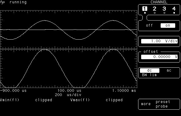
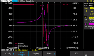
Bode plot on Siglent oscilloscope with non-Siglent signal generator
|
Those program examples were just an exercise in Python before I tackled
Bode plots with my Siglent SDS 1104X-E
and my Agilent / HP signal generators. In fact, that was the
main motivation why I began setting up GPIB and PyVISA in the first place.
|
Some important notes
This is interesting: If the USB-GPIB adapter is connected, and its driver is
appropriately loaded, but no instrument on the GPIB bus is switched
on, PyVISA will hang when list_resources() is called!
A bit annoying if you have both GPIB and RS232 or USB instruments routinely in
use, but they are not all switched on all the time... But the situation
will resolve itself immediately when you switch on any one of your GPIB
instruments. Just so you know, and don't go hunting for some other bug or
failed driver or whatnot, if it happens to you.
Also, it seems that many GPIB instruments go to remote mode when scanned
by list_resources(). Maybe not a big deal, if you're only
using those instruments that you're actually controlling over GPIB. But
this may be annoying in the case of a multimeter, which is universal
enough that you might be using it practically all the time... And then it
also goes remote when some script accesses some other instrument remotely.
So perhaps it's best not to scan the GPIB bus in every script, but rather
hard code the resource names or read them from a config file.
And, of course, all information here is provided without any guarantee
to be correct, and you should not assume that any of the scripts presented
here actually work. The
web interface scripts may be
full of security holes
as well, and should not be placed on any Internet-facing server. Use at
your own risk, and don't blame me if anything bad happens!
Add a power button to the Raspberry Pi
So now I'm running a Raspberry Pi as a lab server just for my own
occasional use. These things are not exactly power hungry, but why not
shut them down anyway when they're not actively needed. It's not like I'm
utilizing my oscilloscopes and stuff every single day. Shutting
the Pi down would be shutdown -h now or something similar.
But how to get the Pi back up without power cycling?
|
One possibly less well known feature of the Pi is that momentarily
connecting GPIO3 to GND will boot up a Pi that has been
shut down. Just google for "raspberry pi power switch"
or something like that (and ignore whatever you find on the Pi 5,
which has an actual power switch built in). You will also find examples
of scripts that
will shut the Pi down cleanly when the same pin is grounded. I set about
installing a power button on the GPIO header the moment I found that
out! While I was at it, I also searched for info about an "On"
indicator LED. It turns out that most GPIO pins maintain their state on
shutdown, but the Tx pin of the Pi's serial port (GPIO14)
remains (mostly) high while the Pi is up, and goes low when the Pi is shut
down. And I wasn't using that serial port for anything.
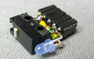
So I took a 2×5 block of female pin header, one microswitch, one
330Ω resistor and an annoying blue 3 mm LED, and soldered this tiny
circuit to plug into the Pi's GPIO header.
|
|
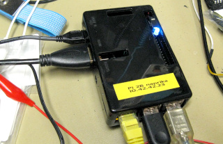
Here's the circuit plugged into the GPIO header. No, you can't really see
much of it in the photo, what with the case and all... The microswitch
protrudes from the opening in the case only just enough to be accessible,
but the annoying blue LED is easily visible. (Happily the Pi does not
contain any blue indicator LEDs of its own, so this stands out like a
sore thumb!)
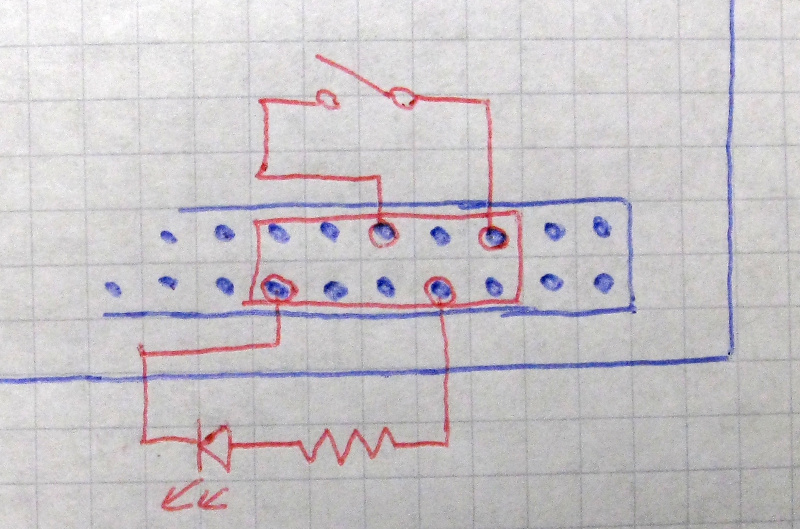
If you really want a schematic of the thing, you'll have to
settle for this ugly drawing.
Figure it out yourself. :)
Some Pies may also need the line "enable_uart=1"
in /boot/config.txt for the power LED to work. Mine did
not. |
I then put the following script into
/usr/local/sbin/powerbutton (and made it executable, of course):
#!/usr/bin/env python3
import RPi.GPIO as gpio
import subprocess
gpio.setmode(gpio.BCM)
gpio.setup(3, gpio.IN)
gpio.wait_for_edge(3, gpio.FALLING)
subprocess.call(('shutdown', '-h', 'now'))
and the following into /etc/systemd/system/powerbutton.service:
[Unit]
Description=Enable shutdown on powerbutton
After=default.target
[Service]
ExecStart=/usr/local/sbin/powerbutton
[Install]
WantedBy=default.target
after which I enabled the service with
systemctl enable powerbutton.service.
Now I don't have to plug in a power supply just to get a network screenshot
from one of my oscilloscopes, and I don't have to ssh into the Pi just
to cleanly shut it down afterwards. Just reach over and press the power
button, as it should be! :) Of course if there's a
power outage while the Pi is shut down, it will boot up immediately when
power returns. That's how the Pi works, so this simple "software"
power button (not even a power switch, mind you) does not completely
mimic, say, a desktop PC's power button. But designing an actual power
switching circuit just doesn't seem worth the trouble. (The Pi 5
has an actual "real" power button, but isn't that machine just
needlessly and wastefully overpowered for this purpose...?)
Updates
Compiling linux-gpib-kernel fails
Gerwin Jedynak kindly contacted me with an important tip. Apparently,
newer Linux kernels (e.g. 6.12.20 which he was using on his Raspberry
Pi 5) have changed some symbol name, and now the linux-gpib-kernel
build fails, at least version 4.3.6. To fix this, you should edit the
linux-gpib-code/linux-gpib-kernel/drivers/gpib/gpio/gpib_bitbang.c
file, and locate the line
if (gpio_request_one (gpios_vector[j], GPIOF_DIR_IN, NULL)) break;
which you should change to
if (gpio_request_one (gpios_vector[j], GPIOF_IN, NULL)) break;
Only the one occurrence of GPIOF_DIR_IN needs to be changed to
GPIOF_IN. After that, the build should work.
I have not yet tested the above, but it serves as a note to myself if I
ever upgrade my GPIB server to a newer Linux
kernel. :) Or perhaps the bug will have been fixed
by then.
Thanks
This is how I got things working. My deepest respect to those who
documented the process before me—all I have done is update the
instructions to use the stock kernel on the Pi. Thanks also to Gerwin
Jedynak for pointing out the above linux-gpib-kernel issue.
Any questions or comments,
I'd love to hear from you by email! And sorry if my Python looks like I'm
coding with my left foot—I'm an absolute, complete, helpless newbie
in Python! :)
Antti J. Niskanen <uuki@iki.fi>