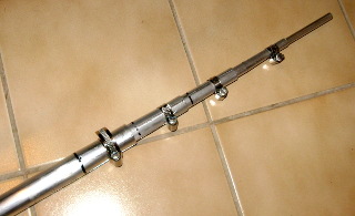
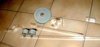
This may be the most difficult stuff to acquire: You need lengths of aluminum tube. The trouble is, you need seven different thicknesses which must fit inside each other! I cut a slot in the upper end of each segment, and used stainless steel hose clamps to tighten it over the next smaller segment. In some of the lower segments I also drilled a hole for a stainless steel bolt through the tubes, so it can better carry weight. Shown in the picture are the five thinnest (uppermost) tubes telescoped inside one another, with their hose clamps. This, with the decoupling stubs shown below, form the antenna upper assembly.
The upper part of the antenna is simply a whip of thinner telescoping tube segments, plus it has decoupling stubs for 15 and 6 meters. These are made of ordinary hookup wire, some clamps made of aluminum sheet metal, and some insulating scraps of plastic. They are held together with stainless steel hardware.
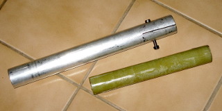
Two fiberglass insulators are needed in the antenna lower assembly (and a couple of other insulators as well, but they don't carry weight, so they don't need to be as strong). The green thing is is a home-made insulator, made from fiberglass fabric and polyester filling. Initially it was hollow, but I filled it with microsphere-polyester mixture, so it won't crush as easily.
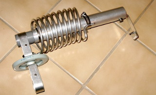
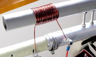
This is the 30-meter assembly, made of a length of aluminum tube, a polypropylene tube insulator, some aluminum sheet metal scraps and stainless steel hardware, a 68 pF doorknob capacitor that I bought from eBay, and a coil I wound from 6 mm thick aluminum wire, using an empty wine bottle as a form.
Luckily, the dimensions of the coils are not too critical. Just make sure the length of wire used to wind the coil is correct. Also try to make the coil as long as specified. It turns out that the inductance will not depend on the number of turns—and therefore not on the coil's exact diameter either. Just try to be in the ballpark.
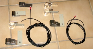
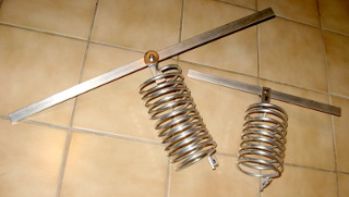
These assemblies hold the capacitors that parallel the 80 and 40 meter coils. The assemblies are made from strips of aluminum sheet metal. The doorknob capacitors (one 68 pF and one 200 pF, made from two 100 pF caps) were bought from eBay and have ridiculously high specifications for voltage and reactive power.
I guess the caps could also be made at home, from double-sided copper-clad printed circuit board material (preferably PTFE).
The resonators for 12 and 17 meters contain just the coils and horizontal strips of metal. They will be attached to the antenna tube so that the horizontal strip is insulated from the tube, and the lower end of the coil is attached to the antenna tube.
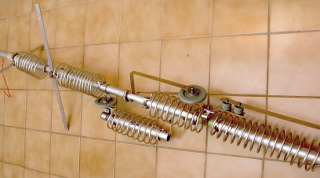
The lower part of the antenna is coming together. This contains all the heavy components: the thickest tubes, the doorknob capacitors, the 80 and 40 meter coils, the 30 m capacitor/coil assembly, and the 12 and 17 meter resonators. I attached three guy wires to the top of this assembly.
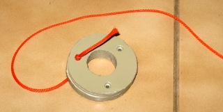
The commercial HF9V supposedly does not need to be guyed to survive reasonably strong winds, but I decided guying couldn't hurt either. Especially since my tube segments are whatever I managed to obtain, and aren't a perfectly snug fit to one another. This ring fits above the antenna lower assembly, just above the topmost coils, and has holes for three guy wires. There is a similar ring two tube segments up, just below midway in the upper assembly.
A coil across the antenna's feed point bleeds off static and also helps tune it on 80 meters. In the commercial HF9V, this coil just hangs there, but I made a support for it from a scrap of plastic tube.
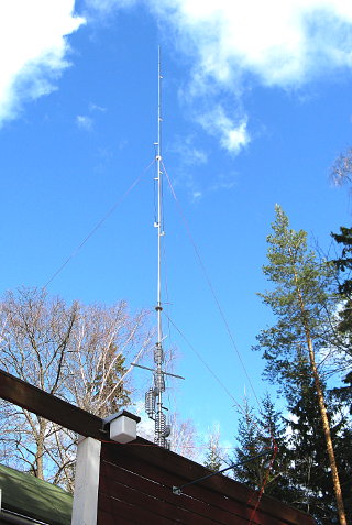
The antenna is complete. It is held in place against my patio fence by U-bolts made of stainless threaded rod, insulated with flexible PVC tube and pieces of plastic from a cutting board. The lowest tube segment is grounded both to a sturdy earth ground electrode (for lightning protection), and to an RF ground of various lengths of radial wires under my patio and circling the patio fence. I'm sure they're not resonant, but it's the best I can do at present. The 30, 40 and 80 m radials crisscross randomly under the patio, and probably work like a generic "counterpoise".
In the commercial antenna, the doorknob caps are exposed to the weather. While this does not seem to be a major concern for HF9V users, I did not like the idea. So I cut the bottom parts from some plastic bottles, and attached them over the capacitors in a half-assed attempt to keep the rain off them.
I just got the antenna up, and have not finished tuning it properly. All
the bands do appear as SWR minima on the analyzer, however. All the
resonances appear initially too high, but the inductors should have plenty
of room for adjustment. My antenna is no longer up, as I have
moved to a new QTH and have not yet begun applying for antenna
permits. For now, I'm only operating portable... A rotateable multiband
Yagi would be nice if I get the permit, but this vertical is still
stashed away in my basement waiting for better times.