<HOME
<Test equipment
<Electronics
Oscilloscope 50Ω termination
How good does it have to be?
 When measuring any really high-frequency signal, it should be properly
terminated. In our world, the de-facto termination is 50Ω resistive,
but most oscilloscopes (at least ones I can afford) have an input impedance
typically around 1 MΩ and 15 pF. That will cause reflections
back into the cable, playing hell with the signal itself, mucking up
amplitudes, and possibly causing the signal source to misbehave. Which is
why BNC feedthrough terminators exist: plug this into your scope, and plug
your signal cable into this. Now the load impedance your signal source sees
should be very close to the desired 50Ω.
When measuring any really high-frequency signal, it should be properly
terminated. In our world, the de-facto termination is 50Ω resistive,
but most oscilloscopes (at least ones I can afford) have an input impedance
typically around 1 MΩ and 15 pF. That will cause reflections
back into the cable, playing hell with the signal itself, mucking up
amplitudes, and possibly causing the signal source to misbehave. Which is
why BNC feedthrough terminators exist: plug this into your scope, and plug
your signal cable into this. Now the load impedance your signal source sees
should be very close to the desired 50Ω.
As always, there are good feedthrough terminators, and there are cheap
feedthrough terminators. Which should you choose? How good does a
feedthrough terminator need to be? Like, for example, would a
cheap BNC tee and a cheap BNC terminator suffice? Like the ones used up
to the 1990s in coaxial
10base2 Ethernet
networks? Like the ones I gathered by the dozens as my university was
upgrading its networks from coax to
CAT5
10baseT and 100baseTx? Would those work? I decided to test.

|
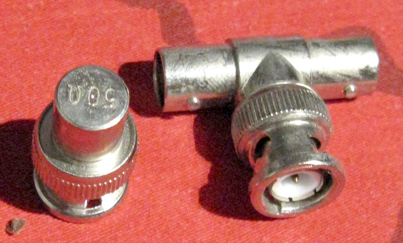
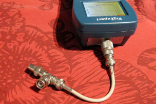
These are the BNC parts I tested. One standard BNC tee (and I don't expect
there to be too much variation from part to part here) and one standard
BNC 50Ω terminator (which may be worse—I've actually bought a
few brand new, only to find them open circuits instead of 50Ω).
Unrelated story: One of those open-circuit terminators happened when I
critically needed it on a 10base2 network, and I did not have
a spare on hand. I did,
however, have a BNC–RCA adapter, an RCA plug, and two 100Ω
resistors to solder to it. Worked like a charm! :)
|
|
I also used a 10 cm or so coax cable to connect these parts to
my RigExpert AA-1000 antenna analyzer and to my
Siglent SDS1104X-E oscilloscope.
These ridiculously short (but sometimes useful) BNC cables are also a relic
of the 10base2 era. Whereas nowadays you have the RJ45 socket in your office
wall, feeding into the CAT5/6/whatever going to the nearest Ethernet switch,
back in the day you'd have two BNC sockets in the wall. One would
lead via RG58 cable towards the nearest Ethernet hub, switch or router,
the other would lead via RG58 towards the next computer in your network
segment. (For the young folk: That's how 10base2 networks were built, in
a chain going from one computer to another, each computer connected to the
chain through a BNC tee! And there were 50Ω terminators at both
ends of the chain. You see how that works from the signal's point of view?)
If you removed your computer from the network, you'd unplug its two BNC
cables from the BNC wall sockets, and connect the two sockets together with
one of these tiny cables to keep the network in one piece.
|
|
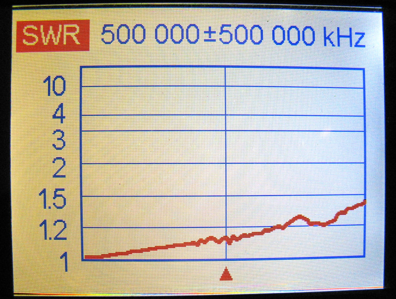
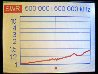
I first tested the BNC terminator alone by connecting it directly to the
analyzer, with just an N to BNC adapter between them. This SWR
curve from zero to 1000 MHz shows how good (or bad) the terminator
itself is.
With an SWR just short of 1.5 at 1 GHz (at far right) it's
actually not too shabby! At 200 MHz (the bandwidth of an
SDS1104X-E if it is hacked to open up its full bandwidth,
turning it into an SDS1204X-E in everything except the print on the
front face) the SWR is below 1.1!
|
|
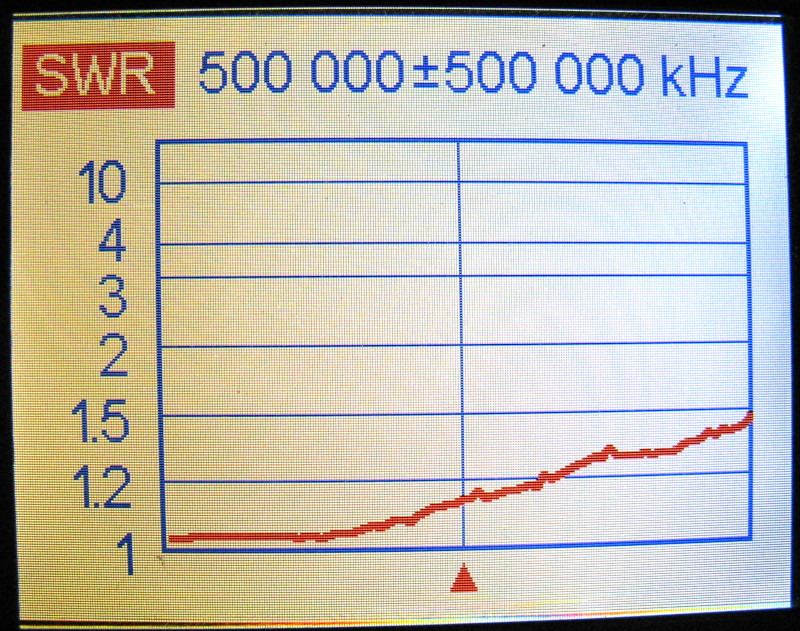
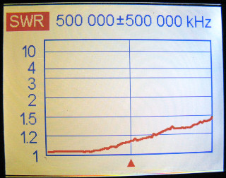
I then attached the terminator to the BNC tee, and that (using the short
BNC cable) to the analyzer, as in the above photo. This SWR curve is from
that combination. Not really too different from the terminator alone, so
it would seem the tee and the cable are fine. Interestingly, the very
lowest-frequency part of the curve is now very close to 1:1. Losses would
explain that, of course. Even with the losses, the curve then begins to rise
more steeply, so apparently the cheap cable and/or tee do have some
effect, but only at significantly high frequencies (above several hundred
MHz). And even a good tee will act as a stub at high enough frequency, so
this is no surprise really. But I'd have to get a calibration kit (with the
necessary open, short and good 50Ω terminations) in order to
dig deeper into this.
But see how the SWR is pretty close to 1:1 all the way up to almost
300 MHz? (The center frequency being 500 MHz.)
|
|
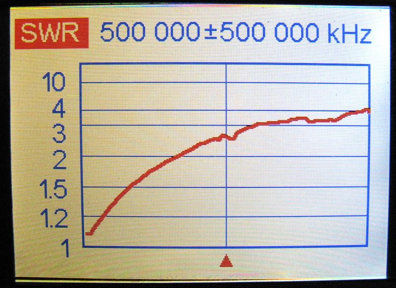
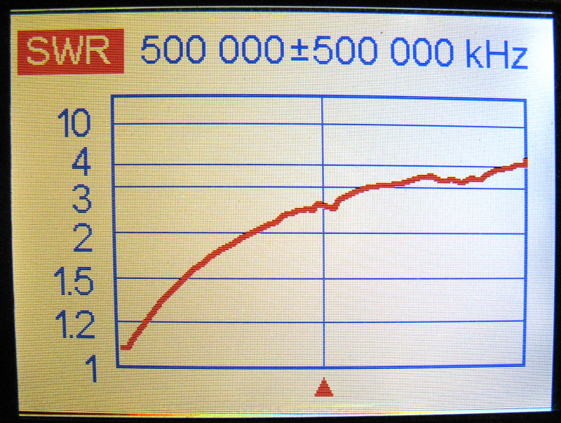
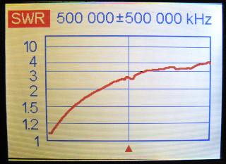
Now add the oscilloscope.
Finally, I attached the "foot" of the tee to my oscilloscope. It
was, of course, switched on. Also, since a click is audible between some
voltage ranges, indicating attenuators being switched in or out of the
circuit, I measured the SWR at each attenuator setting. This one is
with the voltage range of 2–10 V/div (at 1× probe
setting).
As you can see, this curve is way steeper than either one above!
The SWR reaches 1.5 already at 200 MHz, and becomes a rather awful
4 by the time 1 GHz is reached (although such frequencies will hardly
be of concern, unless you can afford a gigahertz bandwidth
oscilloscope—in which case you can afford a more
expensive feedthrough terminator as well!).
|
|
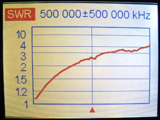
This one is with the voltage range of 0.2–1 V/div. It's almost
identical to the one above. I had to go back and check my settings, but
yes, this is actually correct. I didn't just take a photo twice of
the same SWR curve. :)
|
|
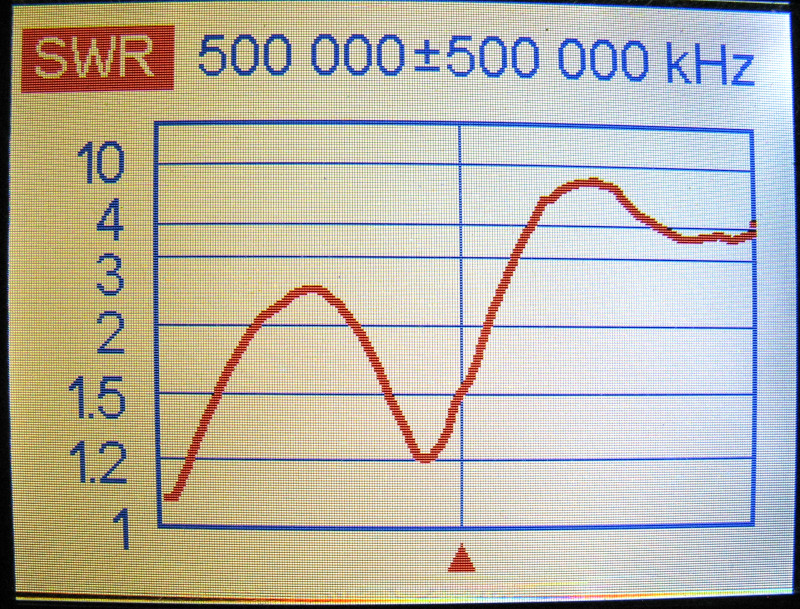
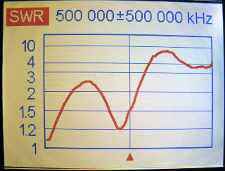
And this one is with the 0.5–100 mV/div range!
Obviously removing the attenuators entirely from the signal chain
caused a much bigger difference than just changing the amount of
attenuation. And it looks like there's some kind of resonance just below
500 MHz. But that frequency is already a tall order for this
100 (or 200) MHz scope. What's actually relevant is the increase in SWR to
about 2 at 200 MHz.
|
So what does all that mean?
In my opinion, it means the cheap 10base2 tees and terminators are just
fine for use at least up to 200 MHz! The SWR was
extremely well behaved in that frequency range... until the
oscilloscope itself was added to the circuit! That means the
measurements may actually be degraded somewhat, but mainly due to the
oscilloscope, not the cheap tee or terminator! So it seems to me
that there's no point in investing in hugely expensive inline terminators,
if the oscilloscope itself messes up the load impedance anyway.
Now, if the oscilloscope itself had selectable 50Ω and
"high-Z" input impedances (as some expensive oscilloscopes do),
those might work much better, as the 50Ω option might be designed
to compensate its input capacitance. (I say "might" because I
don't know if that is the case. I've never had the opportunity to play
with such a fancy scope.) But as long as the scope's input
is very much reactive, even the best feedthrough terminator won't work
better than cheap, repurposed 10base2 hardware!
If you do need better performance, and if you're not measureing ultimately
low voltage signals, you could get a high quality attenuator instead. Feed
the signal of interest through that attenuator to the
tee/terminator/oscilloscope combination, and the SWR will immediately
improve. And in fact, a 20 dB attenuator (which corresponds to the 1:10
amplitude ratio of your typical oscilloscope probe) should work perfectly
well as a feedthrough terminator as it is—without any final
termination following it. With the other end left open, it will
present a 51Ω impedance to the source (calculate it yourself if in
doubt), which means an SWR of just 1.01:1! And an attenuator will find
plenty of other uses as well!
For what it's worth, I did some spot measurements of the complex impedance
at a couple of individual frequencies. Yes, it does seem to become inductive
instead of capacitive at higher frequencies!
| Frequency: |
1 MHz | 10 MHz | 50 MHz | 100 MHz | 200 MHz |
| 2–10 V/div: |
56.7−j0.4 Ω |
55.9−j4.1 Ω |
45.7−j8.6 Ω |
36.4−j3.2 Ω |
36.7+j19.2 Ω |
| 0.2–1 V/div: |
56.8−j0.4 Ω |
55.8−j4.1 Ω |
45.7−j8.6 Ω |
36.4−j3.1 Ω |
36.6+j19.4 Ω |
| 0.5–100 mV/div: |
56.8−j0.4 Ω |
56.2−j4.0 Ω |
44.3−j12.1 Ω |
30.1−j3.1 Ω |
36.5+j34.8 Ω |
So there. I can stop browsing eBay for inline terminators, because they
certainly won't be an improvement over what I already have. (And knowing
typical eBay quality, they'd probably end up worse instead.)
Antti J. Niskanen <uuki@iki.fi>