<HOME
<Electronics
t.Mix MIX 802 / Tapco Mix.60 modifications
Make the headphone and "Control room" volume
control independent of the "Main mix" fader
Add a "Natural Crossfeed Mixer" to the
headphone output
Change the AUX sends from post-fader to
pre-fader
|
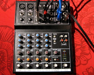
My PC sound card is connected to my Genelec 1029A speakers, both of which
have their own separate volume control—which makes adjusting volume
using those somewhat inconvenient. So I'm using a second hand
t.Mix MIX 802 mixer to control
the volume more conveniently than through the PC's mixer programs. With it
I can also connect a CD player as a program source. Plus I can use the
mixer as a headphone amplifier! Using headphones with my computer would be
completely impractical otherwise.
The mixer was fine for this purpose except for one thing: The headphone
amplifier with its own volume control was post-fader—in
other words, the mixer's "Main mix" fader also
affected the headphone volume. This means that setting the
"Main mix" fader to zero (to silence the loudspeakers)
also silenced the headphones! I really wanted to be
able to control the headphone and "Main out" volumes
independently! Thus: Modify the mixer. I had earlier done
the same
modification on my Behringer UB502, which I had used for the
exact same purpose. Later I did the same thing to my
Behringer MX802A.
I later performed other modifications on this unit: I added
a "Natural Crossfeed Mixer" to the headphone amp, switchable
on and off by the "Tape to Phones" switch (which I had no use for
otherwise). I also made
the AUX sends pre-fader. I have no use for a post-fader AUX send, since
I don't use this mixer for adding reverb effects etc. which should be
faded along with the track itself. However a pre-fader AUX send would allow
me to route one or both mic channels to the AUX output only, without
adding them to the main mix. I can then feed the AUX output to a
sound card input or an amateur radio transceiver, or I can even feed it to
an audio compressor and take the processed audio back into the mixer via
one of the other channels, effectively using the AUX send as an
insert. Overall, for routing audio, a pre-fader AUX send
is more useful than post-fader. It even finds use in
teleconferencing—by routing headset mic audio to the PC via the
pre-fader AUX, I can mix a tiny amount of my own voice into the headphones
as well, to make speaking more natural with headphones on.
|
|
The headphone volume modification
|
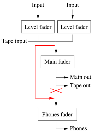
This (much simplified) block diagram shows how the MIX 802,
just like the UB502, is
wired internally. You can see that the headphone amplifier is controlled by
both the Phones fader and the Main fader. The mods
I wanted to do are shown in red: Basically bypass the Main fader
from the headphone amplifier's input. That would provide two independent
volume controls: one for controlling my speakers connected to the
MAIN OUT, another one for controlling the headphones. Or, since the
"CTRL RM OUT" output is also controlled by the Phones
fader, I can independently control the volume of two pairs of speakers
as well.
When I modified my Behringer UB502, I
found the schematic for the Behringer Xenyx 502 online, and
it turned out to be exactly the same with respect to component values
and their reference numbers. I couldn't find a schematic for the
MIX 802, but I did find the schematic for the Behringer
UB802, and it seems functionally almost similar (but not
quite, as one has a fader on the AUX SEND, whereas the other has a
fader on the stereo AUX RETURN). However, when I opened up my
MIX 802, I immediately saw that the components' reference numbers
and values have absolutely no correlation with that schematic. Damn.
|
To open up the mixer, first open the six screws on the bottom, and remove
the bottom panel. Next, pull off a total of 27 potentiometer
knobs—all except the two GAIN pots. Some were rather tight, but
they're just friction fit. Use force where necessary.
Then take off the retaining nuts and associated
washers from all fourteen 6.3 mm TRS jacks and the retaining
screws from the XLR connectors (two screws each) and RCA connectors
(one screw in the middle). Finally, to release the circuit board, open the
five screws holding it onto the top part of the chassis. There are threaded
stand-offs in between the chassis and the board, so it doesn't matter
whether you open them from the top side, or
from the circuit board side. I opened them from the circuit board side, all
except for one, which was very tight—that one I opened from the top.
After this, the PCB came out, and I just had to disconnect the power lead
connector before I could stow away the entire chassis. There were also
spring-loaded washers around the neck of each TRS connector, but these
didn't seem to come off on their own, so I let them be.
|
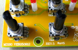
Now that I had the circuit board out for examination, I noticed a marking
of "MIX60" in one corner. Ever hopeful, I searched the net for
"MIX60 schematic", and found the awesomely comprehensive
service manual for the
Tapco Mix.60, which looks like the exact same device! And the component
reference numbers match those on the board. This modification just got
a whole lot easier!
|
|
As in the UB502, the headphone amplifier gets its signal via
the "TAPE TO CTRL RM / PHONES" switch, which is
SW3A/SW3B in the schematic.
It selects either the tape input directly (with the switch in the
down-position), or the mixed signal, post-fader (with the switch in the
up-position). The latter signal is the one that
I want to replace with the pre-fader signal.
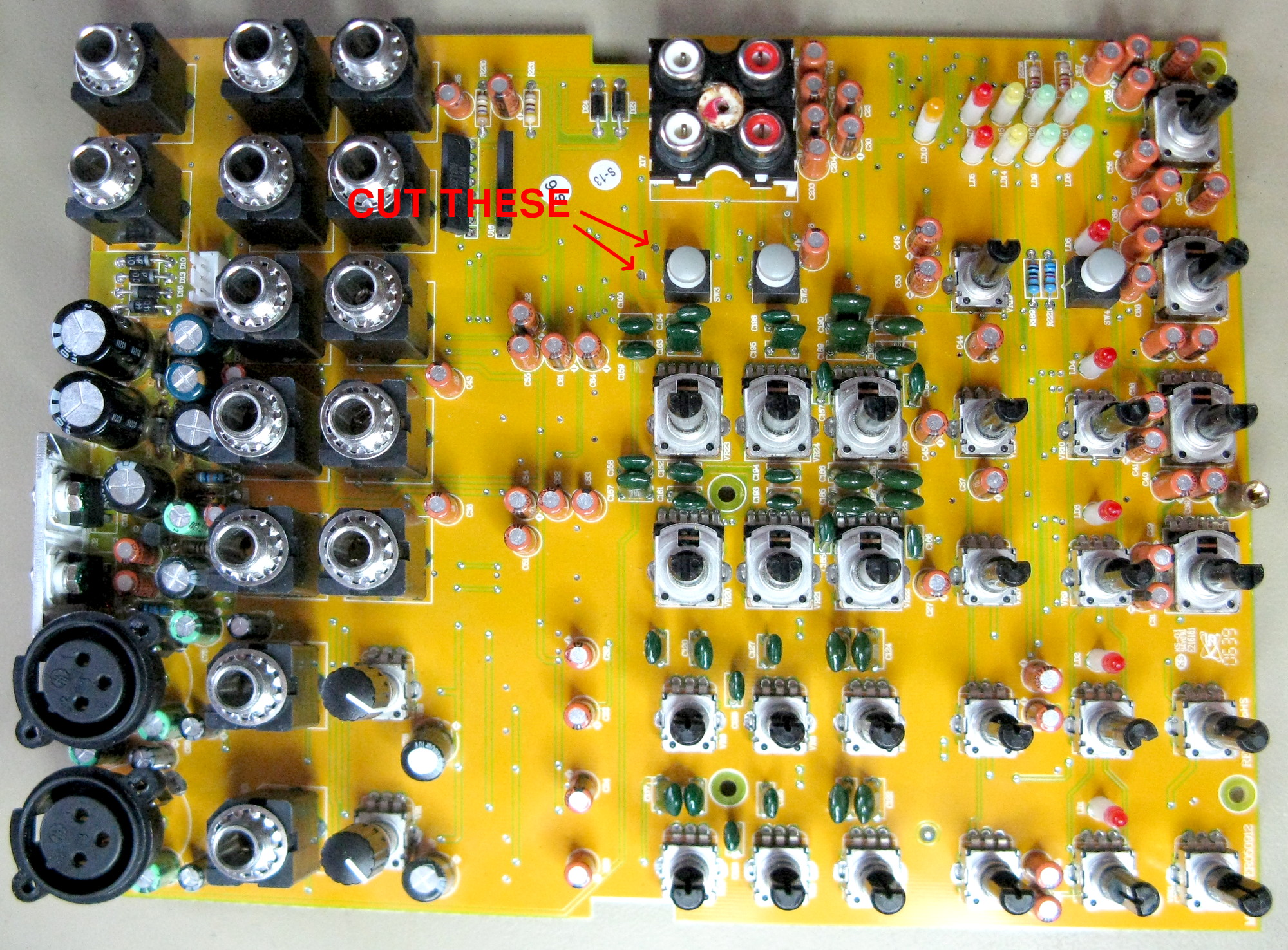
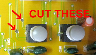
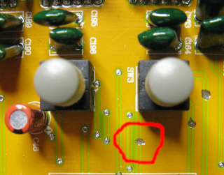
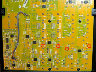
I identified the correct switch terminals (terminals 1
and 4 of SW3A and SW3B in the schematic) by
probing with a multimeter—these terminals have 1 kΩ
resistances to the "TAPE OUT" connectors when the switch is in the
down position. I isolated these terminals from the rest of the circuit by
cutting two traces on the component side of the board leading to SW3
as shown (see the full image here).
These are easy to cut with a Dremel tool and a tiny milling bit.
This has no other side effects—it just cuts the signal to the
"CTRL RM" or "PHONES" outputs, unless the
"TAPE TO CTRL RM" switch is pressed. (On the
UB502, this part of the modification required
cutting two pairs of traces, and soldering a pair of jumper wires.)
|
|
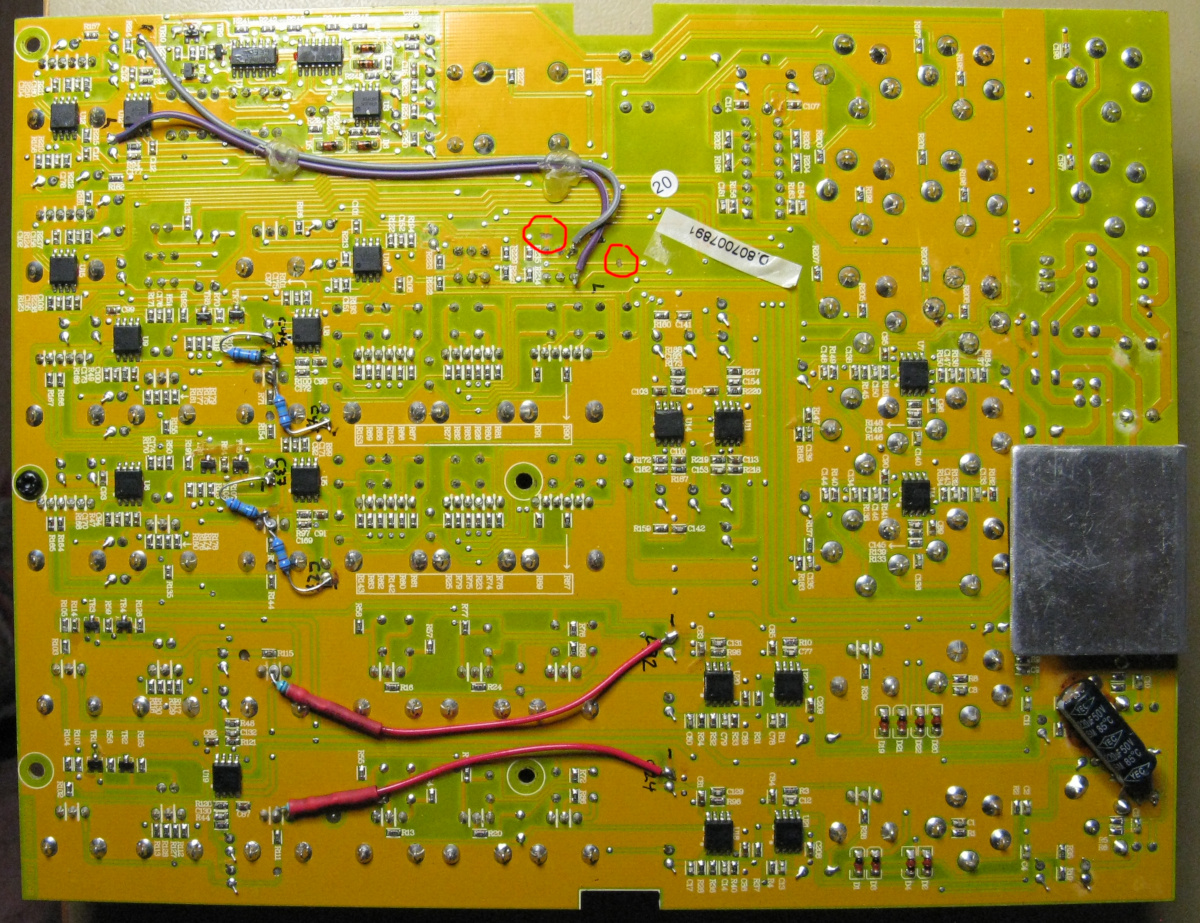
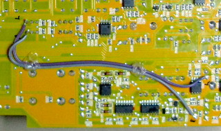
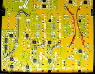
I decided to
take the pre-fader signal from between C56 and R215
(left channel), and between C57 and R214 (right). Jumper
wires are easily soldered on the reverse side of the board,
from the negative legs of the through-hole
capacitors to the corresponding isolated switch terminals (see the full
image here), thus
completing the modification. Two blobs of hot glue help keep the wires
from wandering around.
|
When soldering the jumper wires, make sure you don't short-circuit them
to any other nearby components or board traces. (That should not be a
problem, since they're soldered onto the leads of through-hole
components.) Once done, reassemble the mixer and test it. If all has gone
well, you can now control the main and tape outputs with the "MAIN"
volume control, and the headphone and "CTRL RM" outputs with
their own volume control, independently! Also, since the
"Control room" output is behind the same control, you have two
identical but independently adjustable balanced outputs for two pairs
of speakers. The "Tape to phones" and
"Tape to mix" switches work exactly as before. The level
indicator LEDs, however, are now pre-fader, so they keep blinking along
with the mixed signal even if the "MAIN" fader is turned down to
zero. But blinking LEDs are nice—why should they turn off just
because the music is silenced? Ok, maybe they're not useful anymore for
adjusting levels when mastering a musical recording, but I'm not using
this mixer for mastering anyway.
Adding a "Natural Crossfeed Mixer" to the headphone output
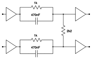
Ages ago I came upon a "Natural Crossfeed Mixer" designed by
Jan Meier, which mimicked the loudspeaker
"soundstage" in headphones with just a couple of passive components.
It was ingenious—the design was so simple it was hard to take seriously,
yet it provided not only mixing between the left and right channels, but also
the phase shift that the brain expects between the left and right ears. It
makes headphone listening much more pleasant, especially over extended
periods. The author's original website seems to have disappeared over
time, but the circuit can still be found online by searching for
"natural crossfeed mixer Jan Meier". You may even find the theory
behind the circuit on some archived copy of the site.
I was once staring at my MIX802 mixer, and pondering in the back of my
mind, where anyone would use the "Tape to Phones" switch—I
had never even used the unbalanced "Tape" inputs and outputs for
anything! Then, out of nowhere, the Meier crossfeed circuit came into mind,
and suddenly it hit me: I could add a Meier crossfeed circuit inside the
the mixer, and I could switch it in and out of the headphone amplifier's
signal path with that otherwise useless switch! If I isolate
the switch from the "Tape In" line, that input can still be
used with the "Tape to Mix" switch if needed. The
"Tape" output, of course, works as before. If, for some reason,
I want the crossfeed circuit's output to an external amplifier, I can get
it from the "Contol Room" output. The main output, of course,
remains unaffected regardless the position of the switch. Together
with the headphone volume modification above, the mixer
would combine the best of all worlds, for listening with either
headphones or speakers!
I made the modification during the next two evenings. I was so pleased
with it, that pretty soon I modified my Behringer
MX802A as well!
|
Meier's design is a simple resistor and capacitor network which will,
of course, perform differently if the input or output impedances vary. The
usual implementation will therefore have op-amp buffers as input and
output stages. Looking at the schematic of the MIX802, I could see
that the main Left and Right buses come directly from op-amps, with just
coupling capacitors in between—certainly low enough in
impedance. (And since the "Tape" outputs are not buffered, but
rather have just 1 kΩ series resistors on them, it stands to
reason that the approximately 1 kΩ load presented by the Meier
circuit should also be acceptable without needing an input buffer.) The input
of the "Phones / Control Room" volume fader stage presents a
30 kΩ resistance—not especially high impedance, but still
an order of magnitude higher than the 1 kΩ or so output impedance
of Meier's circuit. Thus I decided not to bother with op-amp buffers, and
to implement the crossfeed circuit using just the passive components.
Not that adding a TL074 op-amp would be too much bother, as even the
power supply rails are available
ready-made. But the tiny changes to frequency response and phase
shifts caused by minor loading effects cannot be that significant
for its performance. If the exact response of the circuit were really
that critical, then how likely is it that the precise magical
response would be achievable using standard E3-series component
values??? No, not E12, let alone E24, or even E6, but E3!
Simplicity is part of the beauty of Meier's circuit, so let's keep it
simple, unless there's a real reason not to!
|
|
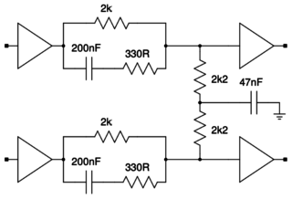
Mr. Meier also designed this bass-enhanced version of the crossfeed
circuit, because decreasing the stereo separation
also seems to decrease the perception of bass, due to some weird
psycho-acoustic effect. I tried both versions, and did notice the same
thing. But which one is more true to the original sound? That seems to
divide opinions on the discussion boards.
If the aim is to mimic loudspeakers, the ideal test would be to compare
crossfeed-equipped headphones to loudspeakers. But that comparison would
really require reference-grade speakers in an acoustically ideal
room—and I have
neither! (Well, my Genelec 1029A speakers are quite good,
but my room sucks.) I do, however, have very nice MB-Quart headphones,
which ought to be very good in all respects, i.e. true to the original
sound. Better than my loudspeakers in this lousy room, surely. So instead of
comparing to the speakers, I simply compared the headphones' sound with the
crossfeed in and out of the circuit. I noticed less difference to the overall
sound with the bass-enhanced version (i.e. it only seemed to affect the
stereo separation or "soundstage"), so that's the version I finally
chose—despite it being so much more complex, comprising all of
six resistors and three capacitors! :)
Of course, the MIX802 also has its own eq, which could be used to fix
any loss in bass, but I'd rather not do that whenever I switch the Meier
circuit in or out.
|
|
I had previously isolated one side of the switch (SW3A and
SW3B) and taken its input from before the Main fader (see the
above headphone volume modification). For this new
modification I had to isolate the other side of the switch, which unfortunately
involved removing the PCB from the chassis again. Bother. Oh well,
this wasn't nearly as bad as dismantling my
Behringer MX2004A!
To isolate the switch, I had to cut three traces, two on the back side of
the board, and one on the front. Having the PCB diagrams available in the
service manual helped a lot here, since one rather critical bit was hidden
underneath the switch itself. You can see the whole PCB
here. The various
wires and other garbage are from earlier modifications.
|
|
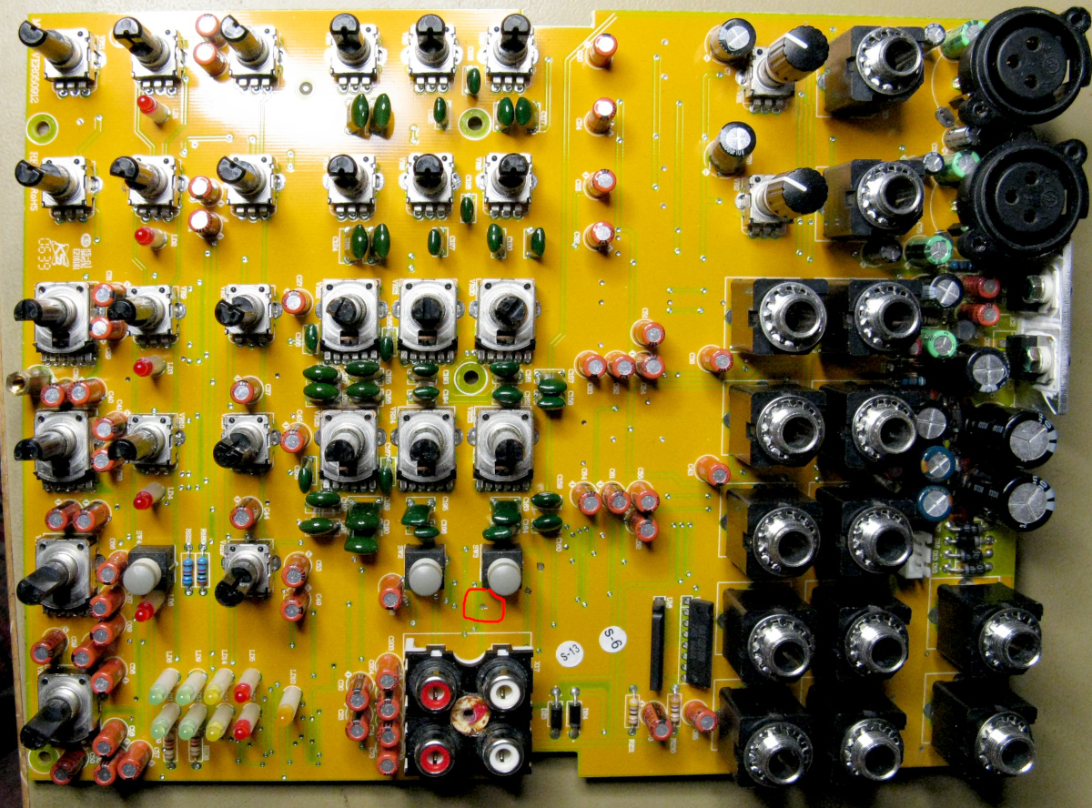
This is the single trace I had to cut on the front side of the PCB. Without
it, I would not have needed to remove the PCB from the chassis.
Bother! You can see the whole PCB
here. (There are two other
cuts near the same switch, which are from an earlier modification.)
Cutting all these traces had the undesired side effect of isolating
the left "Tape Input" from the rest of the circuit, so I
had to add a jumper wire from that input to the positive end of C62
to re-establish that connection.
Interestingly, whereas all other inputs to this mixer are coupled via
47 μF capacitors, the "Tape Input" is wired
directly to the "Tape to Phones" switch, and from there
to the headphone volume control op-amp! No coupling capacitor anywhere!
The buffer before the "Tape to Mix" switch, on the other hand,
is capacitor coupled. And in the Behringer
MX802A, for example, the coupling capacitors immediately follow the
input jacks, i.e. before both the "Tape to Mix" buffer
and the "Tape to Phones" switch. Not that it matters to
me (not after this modification anyway), but I do consider this a design
flaw in the MIX802.
|
|
The basic version of the crossfeed network would have been trivial
to build with leaded components right there on the terminals of SW3.
The bass-enhanced version, however, might have been just slightly messy, so
I built it with SMD components on a scrap of veroboard. That looks
sufficiently messy as well, don't you think?
This "triple-pad" veroboard is of the type that has strips of
three holes connected together. I find it actually more convenient for
constructing tiny projects with SMD, than I do for through-hole
components—I'd prefer five-hole strips for those. Of course, the
holes are unnecessary for SMD, and a bit of a nuisance—I wonder if
there exists a veroboard specifically designed for SMD...?
|
|
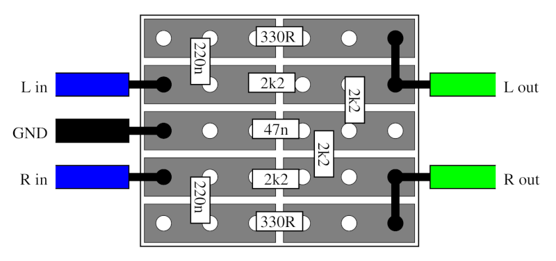
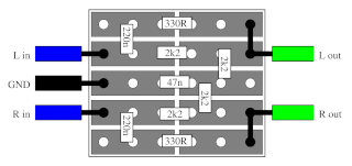
Here's the layout of the circuit.
You'll notice there are no 2k resistors or 200n caps in this layout—I
used 2k2 and 220n instead, as I had those conveniently in-shelf. (I didn't
bother to use two 1k in series or two 100n in parallel, just to keep the
board as small as possible.) Seems to work just fine regardless—I doubt
I'd hear any difference in a blind side-by-side comparison.
|

|
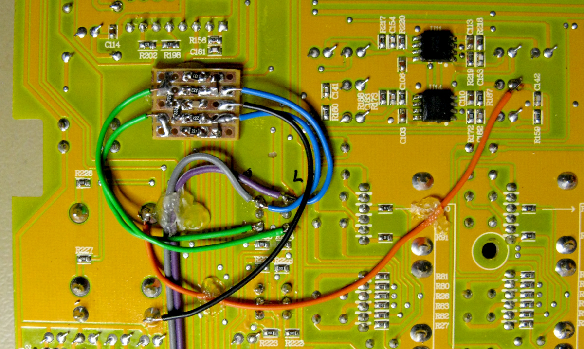
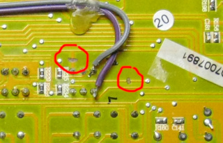
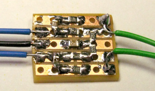
I hot glued the Meier circuit onto the main PCB. The inputs (blue wires)
go to the two upper terminals of the switch (i.e. the terminals on
the side towards all the TRS jacks), and the outputs (green wires) to the
two lower terminals. Try not to get the left and right channels crossed
here. The bass-enhanced version also needs ground (the black wire), which is
available all over the board—I took it from the RCA jacks. The orange
wire reconnects the left tape input, which got isolated by cutting the
traces, as mentioned earlier. You can see a bigger picture
here.
The other two wires (purple and gray) coming to the upper switch
terminals are from my earlier headphone volume
modification. The crossfeed circuit can be installed the exact same
way even if that modification has not been done.
|
Now, with the "Tape to Phones" switch in the down-position, the
Natural Crossfeed circuit is in effect. In Search of the Lost Chord
by the Moody Blues is perfect for testing: House of Four Doors / Legend
of a Mind are now absolutely fantastic with headphones, not to mention
The Best Way to Travel—which used to really hurt my brain without
the crossfeed!
With the switch in the up-position, the crossfeed circuit is bypassed.
Actually, I keep the crossfeed in the circuit pretty much always, and the
switch is quite superfluous. However, I may some day need to use the
"Control room output" as a second main output, so it's good to
have the option of disabling the Meier crossfeed circuit. Also, there do
exist a few albums which are recorded and mixed specifically for headphone
listening, and the occasional psychoacoustic demo on the net—those
also wouldn't work as intended with the crossfeed enabled!
Of course I did this same modification to my
Behringer MX802A as well.
The AUX send modification
In order to use a mono channel as an independent mic preamp—without
feeding its signal into the main mix—I wanted to make the AUX send
pre-fader. That way I could have an effective third output channel,
completely independent of the main outputs.
Also, for remote work teleconferencing, I find it unnatural to speak while
wearing a full headset or earplugs, as I don't hear my own voice as I do
normally (or when using only a one-ear handsfree set). But with a pre-fader
AUX, I can now route my microphone audio through the mixer, and take it from
the AUX send into the computer (via a suitable attenuator, as it's going
into a mic level input). By routing the computer's stereo output also
through the mixer into my headset, I can now mix in just a tiny bit
of my own microphone audio in order to make speaking more natural. It may
not seem like much, but with telco after telco after telco, every single
working day, these things begin to matter.
|
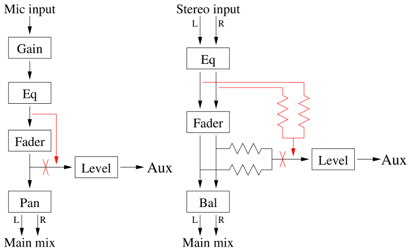
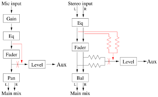
Here's a greatly simplified depiction of the mono Mic and stereo Line
channels with their corresponding AUX sends (click
here for a bigger picture).
As in the above headphone modification, modifying the mono channel is just
a matter of cutting the signal path to the AUX send, and wiring up a new
path from a suitable spot before the fader. Only a bit of wire is
needed to do that.
The only relevant difference of the stereo channel compared with the
mono channels is that left and right are mixed together into a mono
signal by a pair of resistors before feeding into the AUX send. Thus you
can either isolate both resistors and wire them to suitable spots before
the fader, or you can isolate just the AUX send potentiometer, and add
two similar resistors when rebuilding the signal path.
|
|
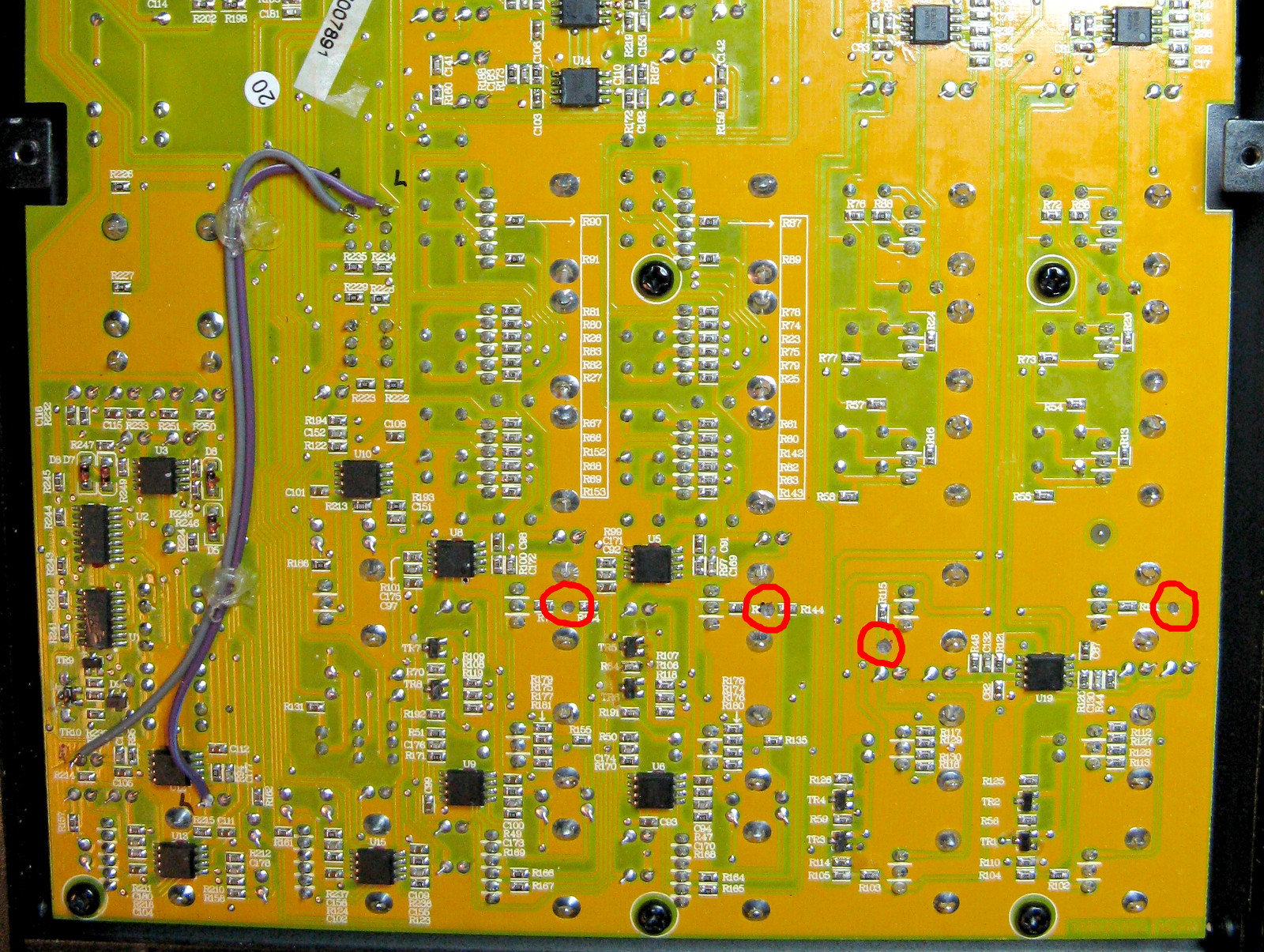
To isolate the AUX send of Mic Input 1, I cut the trace leading
from R111 towards C26. Likewise, to isolate the AUX send of
Mic Input 2, I cut the trace leading from R115 towards
C34. (Instead of cutting the traces, I could also have just
removed R111 and R115 since, as explained below, I actually
replaced them with new leaded resistors. But SMD rework is just a bit
tedious, and cutting the traces seemed the easier way.)
To isolate the AUX send of stereo Line Input 3/4, I cut the trace
leading from R65 towards R144, and to isolate the AUX send
of Input 5/6, I cut the trace from R71 towards R154.
(I could also have just removed R65 and R71.)
See the full image of the cuts here.
The wires you see on the left-hand side of the board are from the
headphone volume modification. The
Natural Crossfeed Mixer modification had not yet
been done when this photo was taken. This AUX send mod will work with or
without either one of the other mods.
|
|
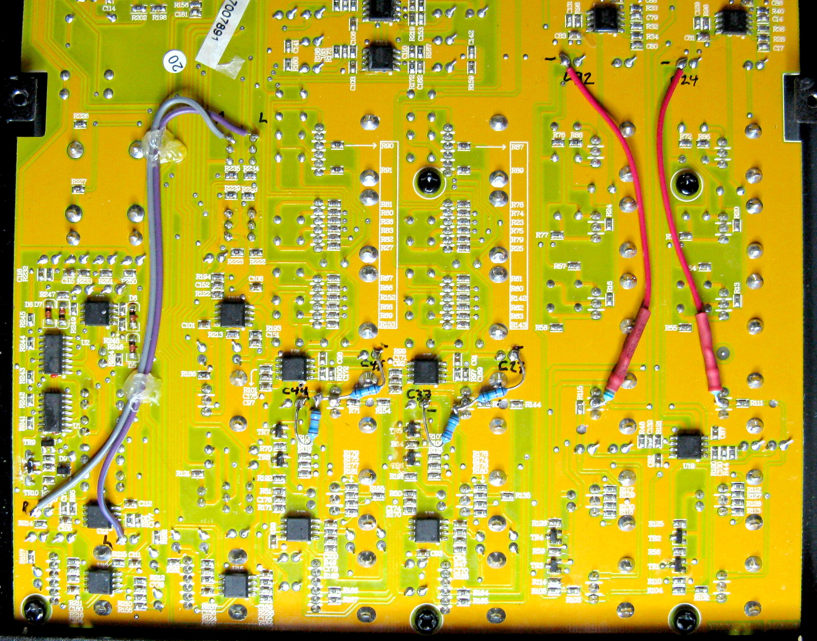
To reconnect the AUX send of Mic Input 1, I would have to solder a
wire to R111, which is an SMD resistor. Soldering on the end of
an SMD resistor is entirely possible (I did that when modifying my
UB502), but it's just a bit tedious.
Instead, I took a leaded resistor
of the same value (6.8 kΩ) and soldered it directly to the AUX
send potentiometer (VR15, center leg), which is a through-hole
component, and easier to solder to. I soldered its other end to the negative
end of C24, which is also a through-hole component. The resistor was
just too short to reach all the way, so I had to extend it with a short
piece of wire. I placed heat-shrink tube over the joint to ensure it
doesn't short circuit anywhere. To reconnect the AUX send of Mic
Input 2, I similarly connected a 6.8 kΩ resistor between
the center leg of VR16 and the negative end of C32.
For Line Input 3/4, I soldered two 15.4 kΩ resistors
from the middle leg of VR17 to the negative ends of C27 and
C37. (From the view of the output, this is exactly equivalent
to the voltage divider of two 10 kΩ resistors R135 and
R144 followed by a 2.7 kΩ resistor R65 in the
original circuit, and
it loads the sources less, and needs one less resistor!) These
components are all close together, so the resistors don't need any
extension wires. Likewise for Line Input 5/6, I soldered two
15.4 kΩ resistors from the middle leg of VR18 to the
negative ends of C45 and C44.
See the full image here.
|
This AUX send modification was very easy to do, as everything was
accessible on the back side of the circuit board—no need to remove
the board, which involves removing all the potentiometer knobs and
connector nuts etc, and then all the reassembly afterwards.
Just open the bottom panel for access. Thanks to Tapco's excellent
service manual, which showed not just the schematics, but the board layout
also, I didn't need to remove the board just to read the component reference
designators on the front side!
I modified the AUX sends of all channels of my mixer, because I have
absolutely no use for any post-fader AUX sends. However, if you want to
modify only selected channels, there's no reason why you couldn't do that.
A word of caution
There's nothing especially difficult about these modifications, but if you
do manage to break something regardless, now have
a broken mixer, congratulations!
So don't attempt this modification unless you
know what you are doing and are willing to take that risk,
and in any case don't blame me for anything
bad that happens!
Antti J. Niskanen <uuki@iki.fi>