<HOME
My Ultracompact, Ultralight 200 mm (8") Dobsonian
|
---->
|
|
(Do you just want to see pictures?)
1. Introduction
I built myself a 205 mm (8-inch) Dobsonian scope from ready-made
optics in 1997. It turned out really well, but it was way too
heavy. 16 kg for the scope itself, plus 8 kg for the mount. A total of
24 kg! Can you guess how eager I was to carry it around? I would have
to rebuild it some time and make it a bit lighter. A truss-tube design
probably.
Then I saw an article in Sky and Telescope magazine describing Gary
Wolanski's ultralight telescope. A truss-tube Dobsonian that could
be taken apart for easy transportation! That got me thinking, and I
realized I could not only make my scope lighter, but really
portable as well! That would be my ticket to deep-sky objects of the
Southern hemisphere also! Thus were set my criteria:
- The scope must be light enough to carry around easily, and it must
not exceed (at least by much) the weight limit of hand baggage on
airplanes. (I don't want to let my scope be banged around in the
cargo hold.)
- The whole thing (excluding the trusses) must fit into a
package small enough to take onto an airplane as hand baggage.
- The scope has to be easy and fast to set up—and collimate!
2. Construction
As is evident from the pictures, my telescope is based very much on
Wolanski's design. The upper tube assembly (figures
1–2) is made from two aluminum rings (I cut them with a jigsaw
without too much trouble) connected with spokes of 10x10 mm aluminum
tube. The lower tube assembly (figures 3–6) is 30x30
mm aluminum angle stock, held together with "Pop" rivets. The trusses
are also 10x10 mm square aluminum tube, just over 80 cm in length.
What is different in my design is that the UTA fits inside the LTA for
transportation (figure 6). The low-profile
rocker box fits on top like a lid. The only components left outside
the package are the trusses and collimation rods. Since the scope is
compact enough to transport as a whole, and thus rarely needs setting
up in the field, I chose a conventional nuts-and-bolts solution for
truss attachment, instead of Wolanski's more exotic approach.
I had been warned that collimation would be a problem with a telescope
designed to be taken apart and reassembled. The secondary mirror is
easy enough to adjust, since its collimation screws are conveniently
located at the top end of the telescope tube. The primary mirror, on
the other hand, is usually a different matter, and requires two
persons for a comfortable adjustment procedure. I have seen somewhere
(Sky and Telescope perhaps?) a solution which allows primary
collimation from knobs located at the top end. My own design (figures 7-9) uses collimation nuts in front of the
mirror cell and detachable collimation rods to provide the same
convenience. As an additional benefit, the heavy primary mirror is
located closer to the end of the tube. In balancing a telescope on a
low-profile Dobsonian mount this can be of great advantage.
3. Finder optics
Located at the top of the tube is a very lightweight Telrad-type
finder (figure 14) made of square aluminum
tubing. I used a piece of microscope slide glass, a plastic magnifier
lens, and a first-surface mirror of aluminized silicon wafer (which is
way easier to cut than glass, and I just happen to have the stuff
available. On second thought, I really wouldn't have needed even to
aluminize it, but I was aluminizing a right-angle prism anyway, so it
was no extra trouble). The bulls-eye pattern was photographed from a
laser printout onto black-and-white negative film.
I also demolished a pair of second-hand binoculars (figure 15) to obtain parts for a finder scope. I
only used up one half of the binoculars, and the other half is still
intact and fully functional. Who knows when I'll find time to actually
build the 10x50 finder... It will have to be located at the bottom end
of the scope in order not to upset its balance, and that means using a
right-angle prism in it, despite the inconvenience of it producing a
mirror-image view. (The prism from the binoculars had an
anti-reflection coating on its hypotenuse side. I could just barely
get total reflection from it, so I aluminized it to be safe.)
This aluminization, by the way, was done by thermally evaporating
aluminum under high vacuum conditions. Of course, every amateur
scientist has a self-built vacuum coating system in their basement,
but working at a semiconductor research lab where evaporators are
standard equipment does have certain advantages... :)
4. Final thoughts
At about 10 kg, this scope is way easier to carry around than the
previous version, which weighed in at 24 kg total. Now it is actually
possible to carry this outside all by myself, which I was very
thankful for when Comet Ikeya-Zhang was visible in March–April
2002. Since this was my first light-weight design and my first
truss-tube design, I overdesigned some parts and ended up with perhaps
a kilo or two of extra weight (especially the LTA materials are sturdy
enough for a 300 mm primary!). But the structure did turn out sound,
and I lost absolutely nothing in stability compared to the old,
heavier monster. When I build a bigger scope, I will definitely use
the same design.
I flew to Australia to see the Leonid meteor storm in 2001, and I
managed to get this scope in usable condition just in time. Yep, the
glorious Southern sky made it all worth while. :)
5. Pictures
The Upper Tube Assembly |
![[PICTURE]](pix/al8in/uta-rings.jpg)
Figure 1: The upper tube assembly rings were cut from
1.5 mm thick aluminum with a jig saw.
|
![[PICTURE]](pix/al8in/uta-complete.jpg)
Figure 2: The complete UTA
|
The Lower Tube Assembly |
![[PICTURE]](pix/al8in/lta-frames.jpg)
Figure 3: The lower tube assembly frames are made of 30x30 mm,
3 mm thick aluminum bracket.
|
![[PICTURE]](pix/al8in/pri-cell.jpg)
Figure 4: The primary mirror cell was cut from scrap 10 mm
thick aluminum. The jig saw could just barely hack this.
|
![[PICTURE]](pix/al8in/lta-complete.jpg)
Figure 5: The completed LTA with trusses attached.
|
![[PICTURE]](pix/al8in/uta-inside-lta.jpg)
Figure 6: The UTA fits inside the LTA for transportation
|
Primary mirror collimation |
![[PICTURE]](pix/al8in/pri-collim.jpg)
Figure 7: The mirror cell attached to the LTA frame. The two
larger nuts will be used for collimation.
|
![[PICTURE]](pix/al8in/collim-close2.jpg)
Figure 8: The collimation mechanism: a novel approach?
|
![[PICTURE]](pix/al8in/collim_schem.gif)
|
Figure 9: Schematic of the collimation mechanism.
A threaded rod is attached to a threaded hole in the primary cell,
using a nut to fix it in place. This is supported with a conventional
spring-and-nut system, from above. The collimation nut is a
"long" nut often used to connect two threaded rods together. The whole
thing is supported from the lower LTA-frame with a piece of sturdy, 5
mm thick aluminum bracket.
The advantage of this arrangement is easy collimation with rods
reaching up to the top end of the telescope, as well as locating the
heavy primary mirror as close to the bottom end of the telescope as
possible.
|
The Dobsonian mount |
![[PICTURE]](pix/al8in/alt-bear.jpg)
Figure 10: The altitude bearings are aluminum/plastic composite.
These are designed also to fit inside the LTA, but I rather leave them out
to reduce weight of the package.
|
![[PICTURE]](pix/al8in/alt-bear-attached.jpg)
Figure 11: The bearings are attached to the LTA so that their
center of curvature matches the scope's center of gravity.
|
![[PICTURE]](pix/al8in/groundboard.jpg)
Figure 12: The ground board is made of aluminum tube and sits
on three junior-sized hockey pucks.
|
![[PICTURE]](pix/al8in/rockerbox.jpg)
Figure 13: The rocker box. When packing the scope for transportation,
the rocker box fits like a lid on top of the LTA.
|
The completed telescope
(Click to enlarge these pictures) |
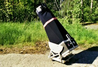
Figure 16: The completed telescope. The pink thingy is a
reflective arm-band, meant to make the scope less invisible to
approaching vehicles.
|
![[PICTURE]](pix/al8in/scope-shroudless.jpg)
Figure 17: Remove the shroud...
|
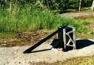
![[PICTURE]](pix/al8in/scope-apart.jpg)
Figure 18: ...take it apart...
|
Figure 19: ...and ready to travel!
|
Antti J. Niskanen <uuki@iki.fi>
![[PICTURE]](pix/al8in/telrad-finder.jpg)
![[PICTURE]](pix/al8in/finder-optics.jpg)
![[PICTURE]](pix/al8in/scope-finished_big.jpg)
![[PICTURE]](pix/al8in/scope-shroudless_big.jpg)
![[PICTURE]](pix/al8in/scope-apart_big.jpg)
![[PICTURE]](pix/al8in/scope-transport_big.jpg)