<HOME
<Test equipment
Finlandia Interface (Efore) electronic load CL 3050B
|
Any time I've needed to sink substantial current, be it from a battery
or a power supply under test, I've had to improvise from car headlight
bulbs or power resistors I have in shelf. I never got around to making
a proper DC dummy load (though I'd already sourced a suitable
el-cheapo volt/amp meter for the purpose), but then I found a vintage
one going to garbage at the
local Hacklab. There was a pile of them, in fact. I plugged one in,
verified the voltage and current displays came to life, and brought it
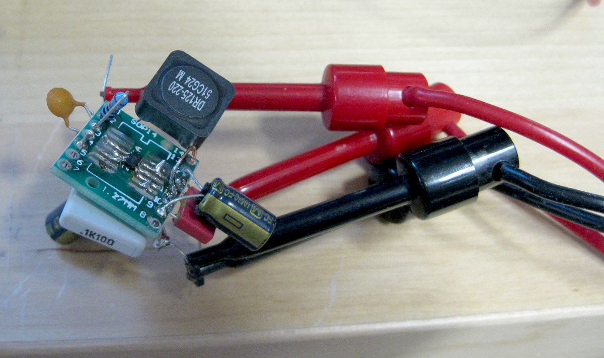
home. Perfect timing for testing an amateur
rocket flight computer's
buck converter I had in the works! Wow, now I don't need to have an
incandescent bulb blinding me while I check out a new power
supply! :)
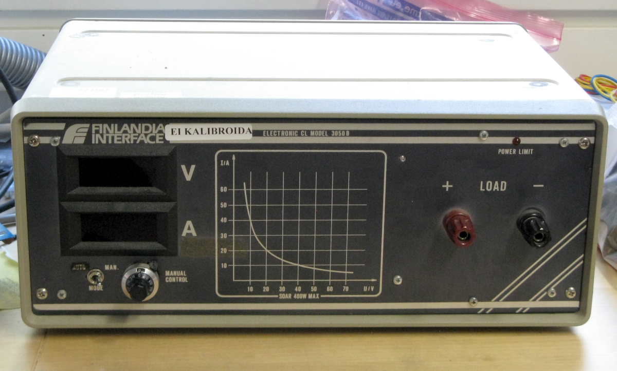
It's a very nice and simple desktop unit manufactured by Finlandia
Interface (which
changed its name to Efore Oy in 1996). The front panel labels it
as "Electronic CL model 3050B, and there's absolutely
no information to be found on it online! No specs, no manual, no
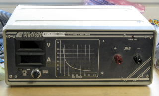
schematics, nothing! But it's simple enough—the front panel has
red and black binding posts (also labeled "+" and
"−", so probably polarity needs to be honored),
two displays labeled "V" and
"A", a "Mode" switch that toggles between
"Auto" and "Manual", a single multi-turn
potentiometer, a "Power limit"
LED, and an I/V curve diagram showing its 400 W maximum
safe operating area. The diagram's axes are labeled up to 70 V and
to 60 A (yikes!), but no
other mention is made of absolute maximum ratings, except in power.
|
|
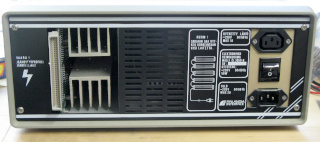
Labeled in some mystery language
|
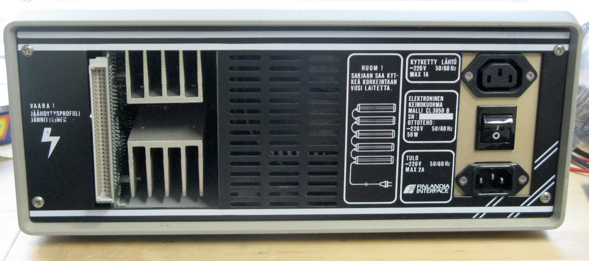
On the back of the unit,
everything is
labeled in Finnish!
The markings state this is
"Elektroninen keinokuorma malli
CL 3050 B", i.e. that it's an electronic dummy
load, model CL 3050 B (slightly
contrary to the front panel, but no matter).
Interestingly, there's a space for a serial number, but nothing
stamped on it—could this be a pre-production or in-house model
that never made it to market??? That might explain why
there's no information on it anywhere.
There's your typical IEC power input
connector (input power specified 50 W)—and an output
connector as well—and the
main power switch. There's a diagram, annotated in Finnish, specifying
that a maximum of five units may be daisy chained through the power
connectors. There's also a prominent multi-pin connector (looks like
DIN 41612,
with 2×32 pins, center row unpopulated),
not labeled in any way. (And there's also a
warning—again in Finnish—that the heat sink, rather easily
accessible by prying finger, is live. I don't know whether it means
it's mains live, or only DC input live. No matter, just don't touch.)
|
But why should this kind of devices be designed to be daisy-chained in
their power supplies? I can only posit that these units are designed
to handle even higher currents by connecting several in parallel through
their input binding posts. So you switch on the
"master" unit, and up to four "slave" units come up as
well. Each unit sinking a maximum of 400 W, that makes a total of
2 kW. I can see that DIN 41612 connector daisy-chained to the
other units with a flat multi-conductor cable with five IDC
connectors. I can also imagine the master unit set to
"Manual" mode and the slaves to
"Auto", allowing one to control how much current is sunk by
the others. Alternatively, that connector might be some
truly archaic computer control connector
(GPIB this
interface is not). Or, perhaps, both—if a "master" unit
can set the current to be sunk by a "slave" unit, so could a
computer, perhaps through a separate interface module.
Anyway, I only use the one unit in its "Manual" mode. With a
lab power supply, I quickly determined that this unit slurps up
constant current, which is set by the multi-turn pot. I
repeat, constant current—it is not a high-power,
programmable resistor, whose current consumption would respond to the
input voltage. But perfect for load-testing that SMPS. The
input binding posts are isolated from the chassis and mains ground /
protective earth, so it should not cause any untoward weirdness when
attaching other instrumentation such as oscilloscope probes.
|
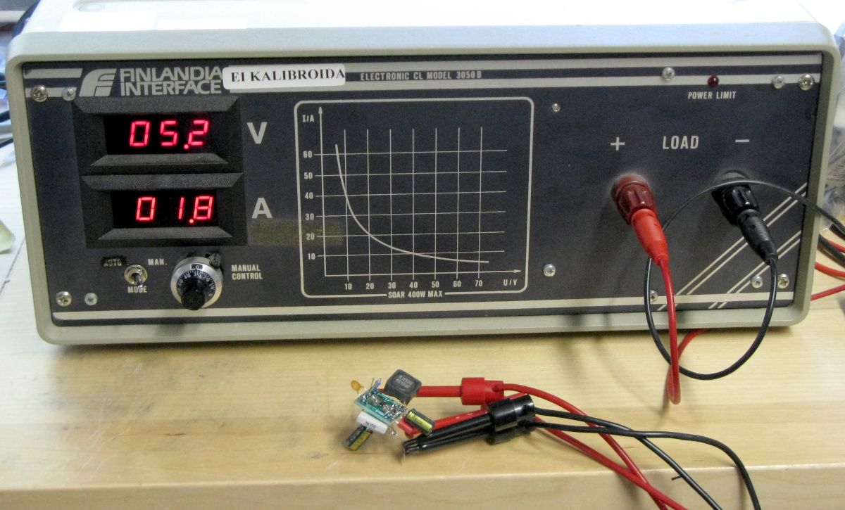
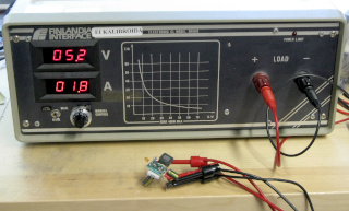
Here's
the unit drawing just shy of 2 A from
the ugliest buck converter
you're ever going to see. The IC is a TPS54202DDC, which is in
a SOT-23 package—hard to prototype on solderless breadboard. So I
whipped up a proto on an adapter PCB intended for SOP14
devices—wrong pitch, wrong everything, but close enough for this
small number of legs. Good enough to check that it works, and approximately
reasonable for thermal testing (i.e. is anything overheating) with
my UTi260B thermal camera.
And yes, at that current, the tiny IC did overheat, and
rather quickly at that, but went cleanly into thermal
shutdown. With this adjustable load, and the thermal camera, it was
fast work to find that at around 1.1 A the IC
hits 100°C or
just above, but continues to operate normally. That's already more than
the current I will need in my application, and once I build the same
circuit on a proper PCB, with the proper thermal considerations
(i.e. big copper pours on the recommended pins), I expect the chip to
keep its cool much better still.
|
|
But no, honestly,
yikes!
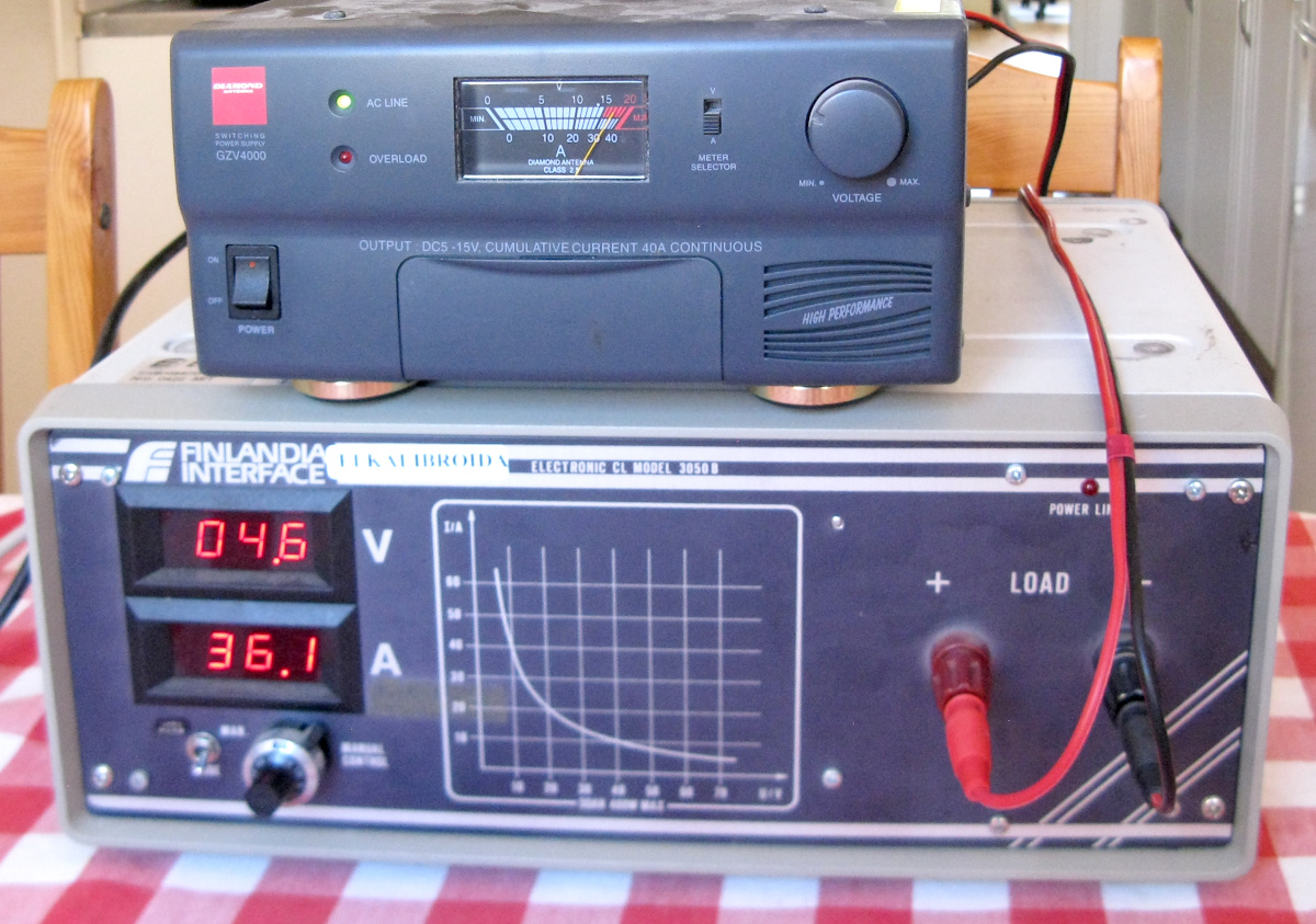
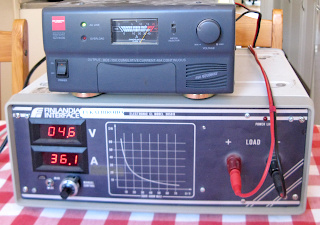
This thing can draw some seriously substantial current!
I mean, my amateur radio
station's Diamond GZV-4000 power supply is rated for
40 amps continuous, but my measly 100 W radio doesn't consume
anything near that even at peak!!! Well, this dummy load
and that power supply are now well and truly tested!
Note that at the typical 13.8 V of an amateur radio station,
40 A would exceed the maximum power rating of the load, which is
why I tested at a lower voltage. Needlessly low, actually, but whatever.
It's the raw amps that worried me more, not the absolute power being
sunk. The latter is just a matter of heat sink, which I believe an
instrument of this era didn't care to skimp on... But I'm not certain that
even the banana plugs I used are rated for 40 A!
|
I only wish the main power switch were on the front panel. I guess
that's easy enough to modify while I'm digging around inside the
instrument—yes, I'll definitely be exploring in there, trying to
find out more about it! Oh, and
if you happen to know anything about this device, especially if you
have actual schematics or such, do get in touch! :)
Antti J. Niskanen <uuki@iki.fi>