|
First I had to charge the radio's battery.
I was too chicken to plug in the universal 100–240 V wall wart
with US plug into a European power outlet... Although many el-cheapo power
supplies are just fine, with the
incorrect plug this would have been impractical in the long run anyway.
So I used my lab power supply instead, set to 10 V. Rumour has it, a
13.8 V station supply cannot be used—apparently it will kill the
charger, or at least the charger will shut down,
unless it is modified first.
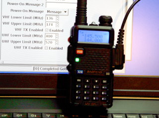
Once charged, the first thing I did was to set
the RX/TX frequency limits. Instead of having to mess around with crappy
Windows
software under Wine,
I was pleased to find that the current
version of CHIRP allows
setting these frequency limits! Like on the
KG-UVD1P, you need to set
144–145 and 432–437 MHz limits in order to get the
144–146 and 432–438 MHz ranges allocated for amateur
use in Finland. (Actually you get 144.000–145.975 and
432.000–437.975 MHz.) Being a bit paranoid, I first ensured all
memories and
VFOs were set to frequencies within these ranges. All went swimmingly
well, despite CHIRP's warning that UV-5R
support is still experimental.
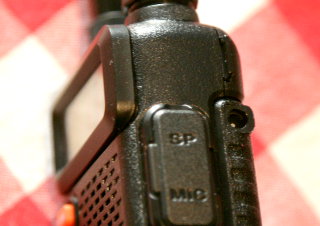
Remember to check
that menu item #32, "AL-MOD", is set to "SITE"!
Accidentally
pressing and holding the button right next to the PTT activates an annoying
Alarm function, which may transmit its alarm noise on the air if set to
anything else! When set to SITE, it only makes audio noise locally.
Annoying, yes,
but at least disabling alarm transmission
doesn't require a hardware mod,
like on the UV-3R.
|
|
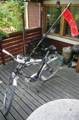
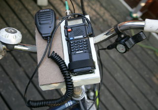
The radio, with its modified speaker mic, was
attached to a vibration isolating mount and thus mounted onto my
bicycle's handlebars (see below). Velcro straps
hold it securely and make for a workable quick-release as well. A
twinlead J-pole antenna, attached to
a fiberglass rod (from a children's bike safety flag) and covered with
heat-shrink tubing, is attached to the front fork of the bike.
I ordered the big 3800 mAh battery to go on the UV-5R. This
gives long operating time, plus it has a 2.5 mm charging jack
(the standard battery doesn't). Thus it will be possible to charge the
radio, without having to dismantle it from the bike mount first for
dropping into the desktop charger. See
below about the charger—the cheap
"charger cables"
available from eBay are dangerous and will explode the battery!
|
|
So what sucks on this radio? The dual watch feature.
That's what. Sure, none of my
El Cheapo HTs has true dual receive, but that's not my beef with the
UV-5R.
What sucks is how the dual watch feature is turned on and off. On my
Wouxun, it's just a single press of the
<TDR> key (or two keys if the keylock is on). On the
UV-5R you have to go through the menu: <MENU> -
<7> - <MENU> - <▲> -
<MENU> - <EXIT>,
what's that... six keypresses?? (Seven,
if the keylock was on.) That's quite a performance, if you just want
to switch off dual watch during a QSO... (The
UV-3R is no better in that regard, but
in that tiny, super cute, ultra miniature rig I was prepared to accept
the inconvenience.) This shortcoming alone makes the
Wouxun way better.
Also, unlike the Wouxun and the
UV-3R, there's no way to make this radio
display its battery voltage.
(Actually, some software versions on this radio might have this feature,
but mine does not. I'm told that holding down the "0" key
displays the battery voltage.)
However, just like the UV-3R, it has a
fairly well behaved battery status icon with 0–3 bars. You
can set the power-on display to read whatever you like, for example your
call sign, but I'd actually prefer it to display the battery voltage,
like on the other two HTs I have.
|
|
Reports abound on the Internet about low TX modulation on this radio.
Many modifications exist to improve it. Audio reports I've received have
not indicated any major problem, maybe just a little on the quiet side.
This may, of course, vary from unit to
unit, or it may depend on the revision of the radio.
The version and whatnot info on my unit are BFB297 (holding down
<3> when powering up) and 130903N (holding down
<6>, also reported by
CHIRP).
The Baofeng speaker mic apparently has
slightly better modulation than the internal mic, but
a slightly "tin can" quality. So when I modified
it to add the 1750 Hz repeater access tone (see
below), I filled up the empty space with open cell
foam. The modification itself also improved the sound quality somewhat.
Now the modulation is, in fact, a bit on the strong side. I'll be opening
up the mic again to install a resistor attenuator some time soon. For the
time being I'll try to talk more moderately and at a distance.
My UV-5R did not exhibit
the display "oddities" observed by Gordon N5GOR
on his website. Apparently these have been fixed since then.
|
|
The big 3800 mAh battery has a 2.5 mm DC jack on its side
near the top. This is for charging the battery, and it is
wired directly parallel to the normal + and −
charging contacts at the back of the battery. You can either drop the
radio, or the battery alone, into the standard desktop charger that comes
with the radio, or you can get a dedicated charger with a 2.5 mm
connector. Such AC-powered chargers are available from eBay, and possibly
they have a higher charging current than the desktop charger, as they are
designed for the big battery.
However, if you search for "Baofeng charger 2.5mm", you mostly
get car charger cables. DO NOT USE THESE TO CHARGE THE BATTERY!
I bought one of those and looked inside—it is a straight cable, not
a charger! It contains no charging electronics at all. Plug that into a
car power outlet, and IT WILL EXPLODE THE BATTERY! (Well, the
battery might contain a safety protection circuit to prevent
it from exploding, but certainly the battery will not be correctly
charged by the car cable.)
|
|
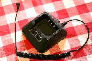
However, the coiled cable and molded 2.5 mm plug were nice, so I
decided to use the cable but to connect it to the UV-5R's original
desktop charger, which is a proper charger. This way I could
charge the 3800 mAh battery through its 2.5 mm DC jack
(to drop it into the desktop charger would require dismantling the
radio from the bicycle mount), albeit with the desktop charger's
standard 400 mA charging current.
So I dismantled the cigarette lighter plug from the cable, preserving
its strain relief piece, and ground a suitable hole into the desktop
charger's case. With a bit of hot glue, I got a nice snug fit.
|
|
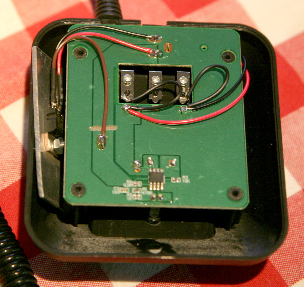
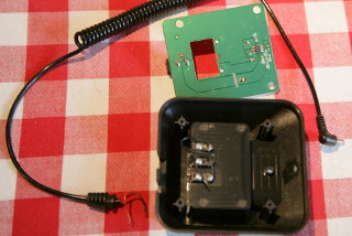
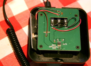
With the cable in place, I simply
parallelled its wires (the red and black wires coming from the right
in the photo, here's an
enlargement) with the charger's + and −
contacts. The T contact is not used by
the charger—it may or may not do something inside
the battery, but in the charger it's not even connected!
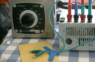
I also modified the charger to accept 13.8 V input
voltage. I simply placed a 7810 voltage regulator (with 0.1 μF
filter caps between input and GND, and between output and GND) on
the charger's input. The charger draws relatively low current, so you
might get away without a heat sink, but I bolted a piece of scrap aluminum
onto it to be sure. There's plenty of room for the regulator and sink
inside the charger chassis. In the photo you see it on the left
(enlargement).
I connected its input and ground (the red and
black wires coming from the left in the photo) directly to the input
DC jack. I milled a break into the pcb trace coming from the DC jack to the
charger electronics (you can see the break underneath the brown wire in
the photo), and soldered the regulator's output (the brown wire) to the other
side of the break (to solder the wire onto the trace, you must first scratch
away the green solder resist).
|
|
Now the desktop charger can be used from my 13.8 V station power
supply, or it could be used from an automobile lighter jack as well.
However, it will not work with its original 10 V wall wart
any more, because the 7810 regulator wants an input voltage typically
2 V higher than its output, i.e. 12 volts. Higher input
voltages, on the other hand, will only cause it to heat up more. At
13.8 V, the outer surface of the charger becomes perceptibly
warm while charging. As the battery fills up and the charging current falls,
the surface grows steadily less warm.
Also the 2.5 mm cable works as planned (although charging the big
battery is admittedly slow—fully charging a depleted battery
can take almost 11 hours—but what's the hurry), and
especially with the strain relief piece still in place, it looks neat
enough to be an original feature of the charger! :)
Just don't try to charge a battery in the drop-in slot and with the
2.5 mm cable at the same time. If the two batteries are initially
at different voltages, harmfully huge currents may flow when they are
first connected in parallel.
|
|
|
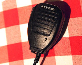
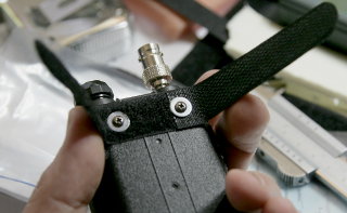
More classy microphones have DTMF keypads and other frills on them, but
the only thing I missed on Baofeng's cheap speaker mic was a 1750 Hz
repeater access tone (or "tone burst").
When using a speaker mic for extra convenience, it's
stupid if you have to reach for the radio itself
just to get a repeater to open. And tone deaf as I am, I
can't just whistle 1750 Hz at will... So I decided to add the desired
function to my speaker mic. (The photo shows the modified mic.
The original had an LED on its front face, the modified version has a
pushbutton switch in its place.)
Interestingly, the Baofeng mic has a silicone seal between the two
halves of its shell, and at the PTT switch. This looks like it's trying
to be waterproof! But then the microphone hole, speaker grille and LED have
no sealing whatsoever—so don't go swimming with it.
Just so you know that any modifications you do won't actually degrade its
resistance to rain.
|
|
You can find the complete (though maybe not completely accurate)
schematic of the UV-5R on the Internet.
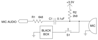
Here is a simplified diagram of the
microphone audio input stage, and the modification being considered. The
mic line in the radio is biased to +3.3 V through a 2.9k resistor.
I wanted to add switch S1 and some kind of "Black box"
which would load the mic
line with a sinusoidally varying current, thus superimposing a sinusoidal
voltage signal onto the line (albeit with a small DC offset, but the
DC blocking capacitor C1 takes care of that). Note that the
pushbutton switch completely
isolates the "Black box" from the circuit when it is not in use,
so it has absolutely no effect on the microphone's performance or
audio quality.
|

|
I opened up the speaker mic, and drew
a schematic of what I found inside.
The modifications are also shown: Firstly, I removed the LED which really
serves no purpose here. This had the positive side-effect of slightly
increasing modulation, and maybe improving it overall a tad. Also, I
ended up installing switch S1 into its hole. Secondly, I installed
the "Black box" (see below) 1750 Hz tone generator
and wired up its pushbutton switch S1.
The precise contents of the "Black box" was the big
question.
There's almost 200 thousand ways to make an audio oscillator
(174341 to be exact), but I needed one that would be reasonably stable,
would produce a sine wave output, and could be powered by the radio's
+3.3 V mic bias voltage. (I did not like the
idea of adding a button cell battery inside the microphone just to power
the oscillator, even though the battery's lifetime would be practically
infinite in this use.) Others have used
Twin-T oscillators for the same purpose, but I'm not entirely certain
how stable they really are with temperature and voltage variations
etc. At
least my initial tests didn't look too promising, so I kept looking for
another solution.
|
|
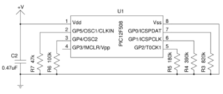
I began thinking about a PIC12F508 microcontroller. It has a
suitable operating voltage range of 2.0–5.5 V, a relatively
low operating current, and it has a precise and stable 4 MHz
oscillator built in. It requires no additional components to work, and I
happened to have
some in shelf, and a programmer for them as well. With its output pins
wired to ground through a set of resistors, as shown in
this schematic, I could program it
to load its supply line with a 5-bit approximation of a sine wave.
This is the "black box" shown above, and the
microcontroller's positive and negative supply pins (Vdd and Vss) are
connected to the positive and negative mic lines of the radio (ring and
sleeve connections on the 3.5 mm connector), with the pushbutton
switch in between.
Capacitor C2 bypasses the PIC's power supply line (a good idea
in general, and especially in an RF environment), and together with
R1 in the above schematic (inside the radio),
forms a low-pass filter. This further smooths out the sine
wave. Also, by selecting a suitably sized capacitor, you can move the knee
of the low-pass filter to reduce the tone amplitude, and thus adjust
it to the same level as the radio's internal 1750 Hz tone.
|
|
So I made
a prototype on solderless breadboard, calculated suitable time delays to
produce as nice a sine wave as possible with the non-linear D/A-converter
formed of available resistors, and started testing. Naturally I
erased the PIC while programming it, thus losing the
factory-set oscillator calibration value. :( So I tweaked
the OSCCAL setting by trial and error, until I got as close to 1750 Hz
as possible (I actually got to within 1 Hz). Here is the PIC firmware
as gpasm source code and
as a compiled hex-file. Since the
oscillator calibration varies from device to device, you really should
compile from source, and change the OSCCAL value until you get it right,
like I did. Or first read the correct OSCCAL value from the PIC,
before you erase the factory calibration, like I did...
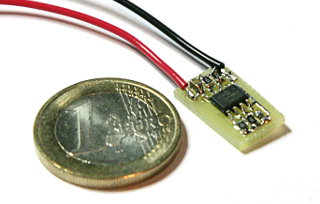
Then I etched a tiny circuit board for the surface-mount PIC and the five
0805 size resistors and capacitor. Larger components are just fine too,
there's plenty of room inside the microphone. (I actually used one smaller
0603-size resistor, because I didn't have an 0805 820k resistor.)
|
|
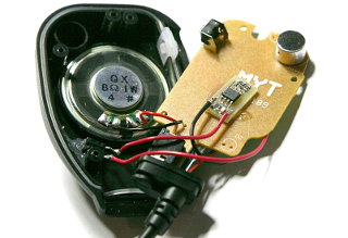
The tiny PCB fits nicely inside the speaker mic. It is hot glued to the
microphone's own circuit board. The pushbutton switch is a normal
microswitch with a suitably long shaft, so that the pushbutton just protrudes
from the microphone. The hole originally occupied by the microphone's
TX LED was drilled large enough to let the shaft through. The
microswitch is also hot glued in place, and wired up to the mic's PCB
and the added modification board.
When closing up the microphone, I filled up most of the empty space
inside with open cell foam,
hoping to improve its audio and decrease the "tin can"
quality. This did not seem to do anything, however. I was also told my
audio had a "dark" tone to is. I swapped the capacitor in the
mic (I don't know its value) for a 1 nF one, big enough to help keep
out RF but certainly small enough not to filter the audio at all. That
also did nothing to improve the audio quality. So it's not broadcast
quality, oh well. Maybe it's good enough for portable rag chewing.
The 1750 Hz access tone works nicely, as it should. There's no reason
why a square wave access tone wouldn't work as well, so this solution
is
overly hi-fi... But the PIC does provide a stable time base, and since it
can do 5-bit DDS, why settle for 1-bit...? :)
|
|
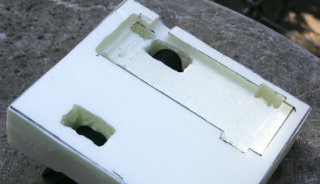
For mounting the radio onto the bicycle handlebars, I made a vibration
isolating mount out of Finnfoam (Styrofoam). It has a hollowed out seat
for the radio, where it is held in place by Velcro straps. The underside
of the foam block is molded to sit nicely on the handlebars. Velcro straps
also hold the mount in place. Holes are made to provide access to the
charging jack on the high-capacity battery, and to enable adjustment of
the volume knob.
The left-hand side of the mount has space for keeping the speaker mic,
and I may also add a clip for a pad of paper and pen.
|
|
All the hollows and through holes in the foam mount were made using a
makeshift hot wire. I used ordinary iron wire, mounted on the edge of
a piece of perfboard (pre-drilled non-metallized circuit board), wired
up to a low-voltage high-current transformer. I adjusted the heat with a
variac, increasing voltage until the wire cut through the foam at a
reasonable rate. (I have used the same kind of hot wire in shaping core
material when building my 16-inch carbon fiber
telescope.)
|
|
The Velcro straps are sold as computer or A/V supplies, and are intended for
keeping bunches of cables neatly together. About half of a strap's length
is of the "hooks" or "rough" gender, the other half
is "loops" or "soft".
In one strap I made two holes with a leather punch. The
strap was attached where the radio's belt clip would go, with washers to
reduce strain on the strap. This is one of the straps to hold the radio in
place. The other strap simply goes around the big battery, at the bottom
end of the radio.
|
|
Here the radio sits in its hollow on the foam mount. Two Velcro straps
hold it in place perfectly firmly. The lower strap is visible across the
battery, the upper strap is hidden under the radio. (Otherwise the upper
strap would obscure the display or some of the keys.)
The radio is on the right-hand half of the mount block. On the left side
there is space for hanging the speaker mic, and I might add
a clip for a small pad of paper for a log and other notes.
|
|
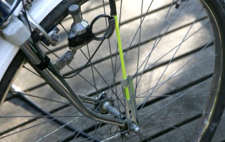
A dual-band J-pole antenna (along the lines of a
DBJ-1
or
DBJ-2)
is mounted on the front wheel fork of the bicycle. The J-pole is made of
traditional 300-ohm TV twinlead and hook-up wire, with an RG-174
decoupling stub for 70 cm. The feedline is also RG-174, with a BNC
connector. An SMA-female to BNC-female adapter sits permanently on the radio.
The wire antenna is supported by the mast from a children's
bicycle safety flag and covered in heat-shrink tubing. The fluorescent
yellow mast is designed to attach at at the wheel axle (front or back).
Here you also see the choke balun on the feedline, right at the bottom of
the black heat-shrink. The choke makes three turns through eight
FT50-43 ferrite beads. No part of the antenna is grounded to the bicycle
frame.
I won't give any dimensions for the antenna, because
(a) they depend on the building materials used, and
(b) I forgot to write down the measurements while
building it... :) Note that the antenna's resonant frequency
will change when it is attached to the mast and covered by heat shrink,
and it will change a bit more when the heat shrink is finally shrunk on
the completed antenna—so tune accordingly!
Warning! Low bridges or tree branches may violently yank the
antenna backwards, hitting you on the head! Unless you enjoy
cuts, bruises or concussion, wear a bicycle helmet!
|
|
|
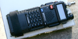
Here the UV-5R is fitted onto the handlebars of my bicycle. The speaker mic
was temporarily installed with bits of Velcro, but it felt like it would
fall of at any time. Now the speaker mic is held in place by its own
clip. The radio itself is mounted
solidly, and the velcro straps that hold the mount on the handlebars turned
out to be perfectly strong as well. They serve as a quick-release mount,
so the whole installation is easy to attach and remove.
Since the antenna is more efficient, and better placed, signals are much
stronger with this set-up, compared to carrying an HT on the belt. Also
the speaker mic is more convenient to use. And when resting in its mount,
it points toward my head, instead of blasting loud RX audio at innocent
passers-by. :)
I even added a bright red "OH2GVB" flag at the top end
of the antenna...
|