The HP 8904A is an old but versatile signal generator offering a variety of waveforms that can be mixed, modulated and tunked in general to no end. Also, with its GPIB interface, it can be remote controlled e.g. to do bode plots with the Siglent SDS 1104X-E oscilloscope. The generator can often be found second hand at a very reasonable price, and ye olde instruments never die—but the electroluminescent backlight of the LCD display does go dim, often to the point of making the display almost unreadable. The contrast of the LCD isn't that great either.
I have such a generator, with such a dim display. I was glad to find a web page by Roberto Barrios which revealed that the display is a standard 2×40 character HD44780 LCD display, and can be replaced with a modern one with very few modifications.
I also replaced the RAM backup battery, as it's supposed to be replaced every five years, and I'd already had this ancient instrument (bough used, who knows how old it was) for some 10+ years!
|
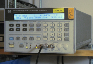
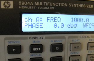
Here's a pretty realistic photo of what the display on my
generator looked like under subdued lighting conditions. Yes, it
honestly was that bad !
Such poor contrast and awful backlighting that it was barely readable!
You had to move around to find an angle with enough contrast to make out
anything! (There's also a dent in the plastic in front of the display
above the "f3" key, but that's hardly the display's
fault.) So I ordered a generic 40×2 LCD module with black letters against a white backlight to replace it with. It cost something like 15 eur on eBay. In addition I needed a 10k trimmer potentiometer for contrast adjustment, and a current limiting resistor for the LED backlight. Those I had already in shelf. |
The LCD module of the 8904A is quite easy to access. (I had already removed the main board for battery replacement, so I had plenty of room to work even without removing the front panel, but during reassembly and testing I ended up removing it regardless.) Open the top half of the chassis (it's kept shut by a single screw at the top of the back face, possibly covered by a calibration sticker). Next pull up the plastic decoration strip at the top of the front aluminum bezel, and remove the three screws exposed from underneath it. Remove the decoration strips at both sides of the bezel (mine were strips of plastic, held in place with two-sided tape—I don't know if this is HP original, or if these have been removed and reattached during earlier service), and remove the screws exposed from beneath them, two on both sides. Finally, remove the three screws from the bottom of the bezel. The front panel will now pop out from within the bezel. Be careful not to yank too hard on any of the cables—especially the output coax cables don't have much slack. You may need to cut a cable tie that's holding the coiled coax cables onto the chassis. This tie is hidden underneath the main PCB, so unless you're removing it e.g. to replace the battery, you may be better off removing the bottom cover from the chassis and accessing it from there. That's just another single screw at the back that's holding the cover on.
Next you must remove an aluminum shield on the inside of the front panel, which is blocking access to the LCD itself. Its top part was held in place by the three screws you removed from the top of the bezel. Now remove the four screws holding the aluminum shield against the circuit board, and remove the shield. Now that the LCD module is in sight, you can remove the four screws holding it in place. Also disconnect the ribbon cable and the EL backlight power cable from the main board, and remove the display module.
|
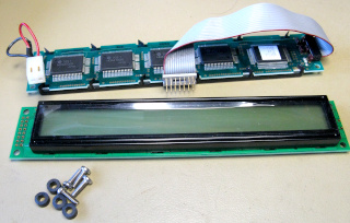
The new LCD module was slightly thicker than the original. The front of
the LCD protruded forward from its PCB about 5 mm in the original,
but 9 mm in the replacement. I made four plastic spacers 4 mm
thick to go on the forward side of the PCB (I epoxied them on so they
stay in place during assembly), and replaced the original
M3×6mm screws with M3×10mm ones. No problem so
far. The aluminum shield, however, will no longer fit over the new LCD. I can't think of any reason for the shield, other than interference caused by high-voltage high-frequency AC needed by the original LCD's EL backlight. Since the new LCD has a nice, clean, low voltage DC LED backlight, I decided simply to leave out the shield entirely. I only replaced its four lower screws, as they seemed to also be holding the keypad PCB in place. If I had proper tools for bending sheet metal, I might have made a new shield to custom dimensions just for kicks. (Alternatively, I could have added spacers for the four screws along the shield's lower edge, and made new holes at its top, with thread inserts and all... But there's hardly any clearance between the lower edge screw heads and the edge of the main PCB, so it might not have fit anyway!) |
The ribbon cable that connects the display module to the main board is terminated in a "3M 3406" connector—a crimp-on ribbon cable connector that plugs into a DIP IC socket ! I couldn't easily source one at short notice, so I cut the ribbon cable from the old display and used that. I hated the idea of stripping and soldering all those fiddly wires individually, so I crimped a 14-pin female ribbon connector on the end, and soldered header pins onto the LCD module. Now display replacement is also infinitely easier, in case I should ever want to swap it again for, say, red/black or white/blue or classic black/green. :)

|
The pinout of the original display module is the same as on any similar
module from eBay, except newer displays have two additional pins for the
backlight. These excepted, only the
contrast adjustment method is different, so the contrast pin (pin 3
on the LCD module, but wire 4 on the ribbon cable!)
needs to be left unconnected from the ribbon cable and supplanted with a
trimmer potentiometer. Roberto Barrios has the potentiometer installed
beautifully in his original
modification, and I followed his example, although it's possible that
modern LCDs would work just fine with pin 3 unconnected entirely.
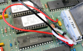
You can see in the photo that
I've cut the 4th wire just short of the ribbon connector. Also the backlight needs power. Pin 15 is positive and pin 16 is negative (these pins did not exist on the original LCD module). These can be connected to the module's +5V and GND (pins 2 and 1) with a suitable current limiting series resistor. The resistance needed will depend on the module used—mine looked good at 20 mA, using a 68Ω resistor when running at 5 V. (That resistance seems rather low—perhaps this module is intended to use 5 V directly, i.e. has the series resistor built in? Yours may be different!) Roberto's version looks so much better, though. My hat is off to his soldering skills! Here's a closup of mine... :( |
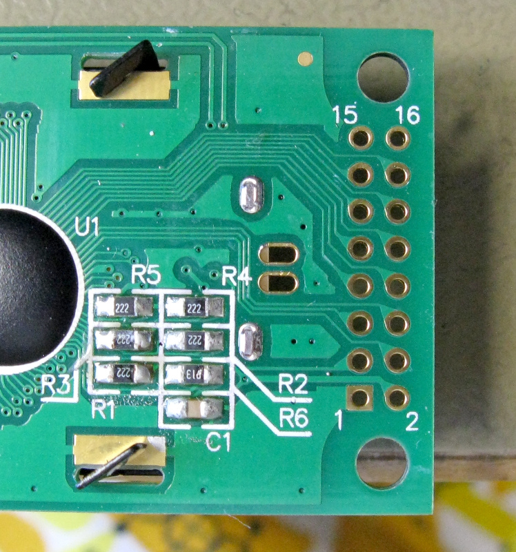
Note, while connecting the individual wires to the new LCD module, the slightly "odd" numbering scheme imposed by HP attaching the connector on the "wrong" side of the PCB! Wire 1 (the one with the stripe) connects to pin 2 of the module, whereas wire 2 connects to pin 1! Wires and pins 3 and 4 are likewise "crossed", as well as 5/6, 7/8, 9/10, 11/12 and 13/14. So, since pin 3 is the contrast pin on the LCD module, it's the 4th wire of the cable which isn't connected anywhere! (Here's a photo of my LCD module's pinout, as seen from the back side of the PCB, in case your module, like HP's original, isn't marked with pin numbers.) If there's any confusion, or possibility to go wrong, please double check with a multimeter! Might not be a bad idea to draw a diagram of the LCD's pinout and the other end's connector, and label which pin was connected to which, before proceeding with anything.
|
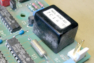
The original LCD module had an EL backlight panel, which was powered by an NEL-032-46 high voltage module on the main board. Whereas Roberto Barrios suggests simply leaving the backlight cable disconnected, other voices on the Internet suggest these modules may not like being operated without a suitable load. Not knowing if the HV module would fail cleanly (i.e. just stop working) or not (i.e. produce lots of black smoke), I decided to desolder and remove it from the board altogether. That was no big deal, since I had already removed the board anyway for replacement of the RAM backup battery. If you're only replacing the LCD, you'll have to decide for yourself. It's not a terribly big chore. |
|
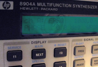
Here's the instrument now, under similar subdued lighting as in the first
photo. The display is bright and contrasty and very easy to read. (Even the
dent in front of the display is less visible now!) Like Roberto said,
"it's a joy to use". (Although nowadays I mostly use this
instrument remotely over GPIB.) The entire modification (with the battery replacement below) took a couple of hours off-and-on during several evenings, mainly because I generally like to sleep on things before doing anything irreversible. And it made a world of difference for the usability of the instrument! I highly recommend this modification, but take no credit for it myself. Roberto Barrios showed how to do it. |
|
The HP 8904A has an internal battery backup for the system RAM. If this
battery dies, the system loses several internal settings and will no longer
operate properly or will no longer have all the options you paid for. Which
is why HP recommends replacing the battery every five years. Well, I'd
bought this instrument used, and I've now had it for over ten years!
High time to replace the battery, then? I was opening up the instrument
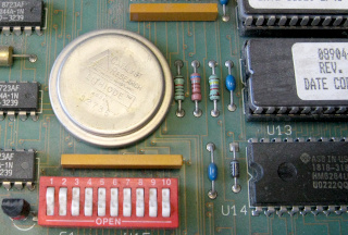
anyway to replace the display, so I did this as well. There are (at least) two versions of the main board with two different kinds of batteries. Mine was the older version, with a huge button cell soldered onto a central area of the board. (The newer version has something like a CR123A cell with leads, soldered near the edge of the board.) But unlike stated in the service manual, there were no coax cables soldered directly to the board, hindering its removal. The coaxes were fitted with some kind of SMA-like connector (SMC perhaps?) and were easily disconnected so I could remove the board completely and work on it more conveniently. |
|
Roberto Barrios also has a web page
on other HP 8904A
repairs, including battery replacement. He suggests
using the biggest lithium button cell there is, a CR2477, in a
button cell holder. Alas, I could not source a suitable holder right
now, but I did locate a holder for a CR123A battery. A CR123A has a
nominal capacity some 1.5× that of a CR2477, so this should be at
least as good a replacement, ugly though the adapter
turned out to be. There's plenty of room
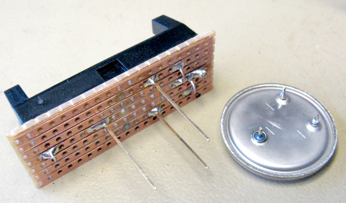
for it inside the instrument's chassis. I hacked up the
adapter out of the CR123A holder, a piece of veroboard, and three pins
from some really tall header. The two positive pins are
spaced 400 mils apart, and the single negative pin is 500 mils from
their center point, per the original button cell's pinout.
Here's a bigger photo of the
adapter. The original battery still had a voltage of 2.77 V—not too bad if it's really a 2.8 V cell as HP claims in the service manual. And it might actually be—it's a "Lithiode" model S2736 made by Catalyst Research. Word on the Internet is it's actually a lithium-iodine battery, used also in some of the earliest pacemakers! Wow, never seen one of those before! As a replacement, a standard modern lithium battery at 3.0 V or even at 3.6 V will be perfectly safe, since with the instrument powered up, the RAM operates at all of 5 V anyway. |
|
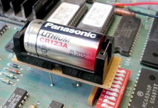
This adapter is significantly bigger laterally than the original battery, and it actually overlaps some other components on the board. Normal header pins would have been far too short to do this, but the 22 mm tall header I had in shelf (I have no idea why) is perfect. There's even room to comfortably access the DIP switches, if ever need be. The pins are also stiff enough not to wobble much under this tall and relatively massive structure. Bits of wire might not be sturdy enough! |
|
Note that you must follow the procedure detailed in the Service Manual
in order to provide 3V voltage to the RAM while you are replacing the
battery ! If you simply desolder the original, the RAM will already
have lost its contents before you install the new battery, requiring a
tedious procedure of reprogramming serial numbers and options. Providing temporary power involves soldering a resistor and some wires to a nearby capacitor and hooking up a temporary 3V battery to those. I had some ready wires with matching 2-pin JST RCY power connectors in shelf, so I soldered the male to the capacitor, and the female to a 2×AA battery holder with the specified 10 kΩ resistor in series. When finished with the repair, I simply left the male connector in place, so the next battery change will be trivial, involving no soldering. I tied the wire to one of the PCB support posts so it won't rattle around. |
It's remarkable how tedious HP has made this battery replacement, although it's supposed to be a routine maintenance procedure performed quinquennially (yes, that's a real word)! Why not have the battery in a holder, and include test point pins for injecting temporary power? I generally love ye olde HP instruments and the way they're built, but this one almost smells like the planned obsolescence that today's HP pushes on their consumer printer customers... (No, that's too cruel. NOTHING smells like today's HP 's practices do.)
Of course, I take no responsibility for the correctness of the above information, and if you decide to modify your own instrument, you do so entirely at your own risk. Let me know how it turns out.