<HOME
<Test equipment
<GPIB on Raspberry Pi
SDS1104X-E Bode Plot with non-Siglent signal generators
e.g. the HP 8904A Multifunction synthesizer
or the Agilent E4421B ESG-A RF signal generator
or other RF generators that understand standard SCPI commands,
over GPIB, serial/RS232, Ethernet/VXI-11 or USB/USBTMC buses!
See this page on how to set up GPIB
on a Raspberry Pi! If that's already done, or if you're controlling
your RF signal generator over serial/RS232, USB/USBTMC or
Ethernet/VXI-11, keep reading! (Or if you don't want to read further,
just download sds_pyvisa_bode.py.)
 I finally decided to pay up and get myself a modern oscilloscope, the
Siglent SDS1104X-E. Not only does it have exceptional value for
money, it is easily modified into the 200 MHz version (or so I hear,
I have not done that myself—at least not yet). But the clincher
for me was the Bode plot function. Ostensibly, it requires a Siglent
arbitrary waveform generator to work (which also have great value for
money), but I began thinking... Could I use one of my existing signal
generators to emulate a supported Siglent AWG, using a microcontroller or
a Raspberry Pi to translate SCPI commands between the two?
I finally decided to pay up and get myself a modern oscilloscope, the
Siglent SDS1104X-E. Not only does it have exceptional value for
money, it is easily modified into the 200 MHz version (or so I hear,
I have not done that myself—at least not yet). But the clincher
for me was the Bode plot function. Ostensibly, it requires a Siglent
arbitrary waveform generator to work (which also have great value for
money), but I began thinking... Could I use one of my existing signal
generators to emulate a supported Siglent AWG, using a microcontroller or
a Raspberry Pi to translate SCPI commands between the two?
Well, it turned out that Dmitry 4X1MD
had already had that idea, and had done all the heavy work for me! There's
a long EEVblog discussion
on the subject, and
his Python code does
exactly what I wanted: it identifies itself to the oscilloscope as a Siglent
AWG, and then translates commands sent by the oscilloscope (over Ethernet)
into commands that several other non-Siglent arb generators (connected
over a serial/RS232 interface) can understand. All I would
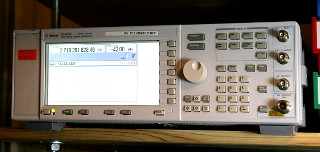
have to do was to write a simple "driver" module to interface
with my Agilent E4421B ESG-A series RF signal generator, which can
produce signals from 100 kHz upwards, way past the scope's maximum.
It is not an arbitrary waveform generator, but the scope only ever
requests sine waves from them anyway. The only real limitations are that
this generator will not work down into the audio range, and it only has
one output channel, so a splitter
will be needed to provide a signal both
into the DUT, as well as into the scope's reference input. (Pretty soon
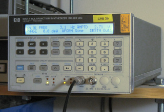
after that was working, I added support for my
HP 8904A
multifunction synthesizer as well. That works from 10 Hz up to
600 kHz.)
|
Dmitry's code includes a "dummy" driver which only responds
to the oscilloscope's commands and reports its activity on the terminal,
without actually interfacing to any signal generator. I used that driver
as a first test, connected the oscilloscope onto my network, and saw that
it would indeed happily generate a Bode plot (albeit
one showing noise only, as there are no signals to measure), apparently
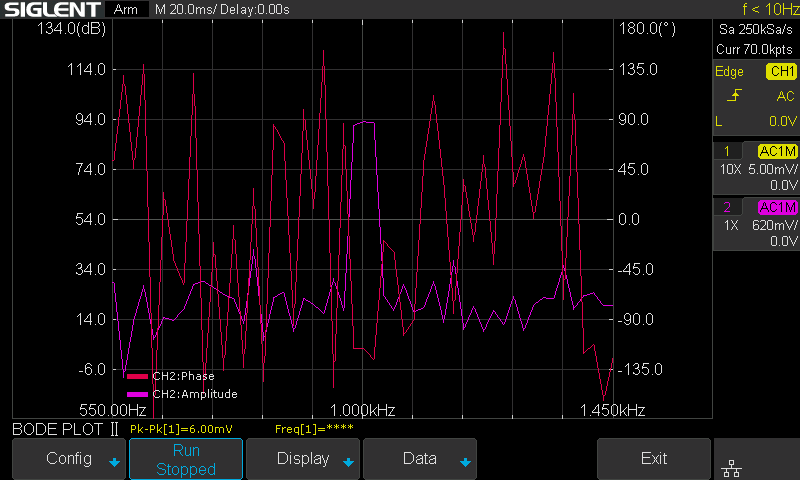
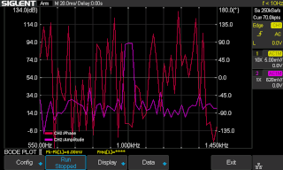
convinced that it's communicating with some model of Siglent AWG. On a whim,
I connected a probe to CH2, hooked it up to the probe compensation
terminal, and made a Bode plot
around its 1 kHz frequency. The phase plot (red) is
garbage, of course, as the reference channel (CH1) was unconnected,
but the amplitude plot (purple) shows a clear peak at 1 kHz! The
Bode plot function apparently uses frequency discrimination (probably the
same FFT routine that's already built into the math functions) instead of
just measuring a simple and stupid peak-to-peak amplitude of the raw
input signal.
|
|
The SCPI commands needed to control the RF generator are extremely
basic:
*RST and SYST:PRES to reset the generator
to its default state
OUTP ON to turn on the output
FREQ 12400000 HZ to set the frequency to 12.4 MHz,
for example
POWER 8.1 DBM to set the output amplitude to 8.1 dBm,
for example
SYST:ERR? to check for an error
These commands are so basic, in fact, that I'd be surprised if this
driver wouldn't work with pretty much any RF signal generator that
understands SCPI!
|
All seemed easy enough, but when I began to examine Dmitry's code, I
couldn't make head or tail out of it. :) Granted,
I'm a total newbie with Python, I don't know anything about
object-oriented programming, and I've never been involved with
programming projects of any significant size. No doubt more experienced
programmers would have no problem with this. But also, I was intending
to use the PyVISA library
for communicating with the generator over GPIB, and that required
Python 3.6+. Alas, Dmitry's code did not run on Python3. Eventually I
bit the bullet and rewrote the entire
code in my own style (i.e. in simple linear fashion) using
Python3 from the start. I learned a lot about sockets and servers, and
about Python in general, in the process.
|
I first wrote the program to work with my Agilent E4421B
RF signal generator, and later added support for my
HP 8904A multifunction synthesizer.
I tried to keep everything relating to the RF generator as model agnostic
as possible, in the hopes of having the code work as-is with any RF
generator that talks kosher SCPI. The older 8904A, however, uses
its own command language, so it's a special case. The program will detect
the 8904A based on its ID string and use its specific commands.
With any other generator, the program will use the generic SCPI
commands shown above.
|
There are some design choices the user needs to be aware of:
- Except for the HP 8904A, the program does not check the
generator's make and
model against any database of supported or unsupported generators.
It either will work, or it won't.
- No frequency or amplitude limits are hard coded into the driver!
The oscilloscope will happily draw grabage output if trying to work
outside the generator's supported ranges.
- Any errors reported by the generator are only relayed to the
terminal where the program is running, so it may be good to watch.
The output messages fall under various "log levels".
Unless there's strange problems occurring, it's best to use the INFO
level, which will only report real problems such as out-of-range
errors from the generator. The HP 8904A will not report
any errors to the terminal, but will beep instead.
- The signal amplitude assumes a load of 50Ω! Since the
program cannot know what kind of of splitter is used at the
generator's output, and what terminations (if any) are installed at the
oscilloscope's inputs, the user is responsible for compensating the
signal amplitude correspondingly.
- The HP 8904A driver tries to drive both outputs of the
generator with the same settings. If the generator only has one output,
a splitter of some kind will be needed.
- For some reason, the oscilloscope never commands the generator to
turn its output OFF, but the program does that when execution is
ended with Ctrl+C (but not if execution ends due to some error, probably).
The relevant limitations for the Agilent ESG-A series are:
- A minimum frequency of 100 kHz (the scope's Bode
Plot II minimum frequency is 10 Hz).
- A maximum amplitude of +20 dBm into
50Ω—just over 6.3 Vpp before the power
splitter. That means about 3.2 Vpp after, whereas the
Siglent generators can provide up to 20 Vpp on both two channels.
The limitations HP 8904A are:
- A maximum frequency of 600 kHz.
- A maximum aplitude of 10 Vpp into 50Ω—more
if the DUT is high impedance and no terminations are used.
- Some HP 8904As have two output channels (OPTION 002), but mine
is missing that option, so a splitter is needed.
|
I wanted to control both signal generators through the GPIB bus, because that's
the way they're connected. I have several older instruments connected that
way, in fact. And that's one reason why I chose to
use the PyVISA library.
The E4421B does also have a serial interface,
so I could have used that exactly like the other drivers do in Dmitry's
software, but PyVISA has the advantage of transparently supporting
all GPIB, serial/RS232, USB/USBTMC and Ethernet/VXI-11
interfaces!
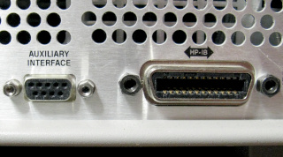
By the way, the E4421B's serial port (labeled "AUXILIARY
INTERFACE") is a 9-pin female D-connector, which one might plug
straight into a PC's serial port with a straight cable, just like
one would connect a modem. Or one might plug a USB-serial
adapter directly into that port. But no, that would be too logical!
In the manual, Agilent specifies you need to use a straight cable
plus a null modem adapter and a female-female adapter to
make the connection (and they specify Agilent part numbers so you can order
them at exorbitant prices). In all, the pinout is the same as on a
PC host, but the gender is opposite! Talk about non-standard...
Was this an actual design choice, or a simple engineering booboo?
|
I dedicated an old Raspberry Pi 3B (soon replaced with a Pi
2B I found in my cupboard, to leave the more powerful 3B for more
demanding use) to serve as the interpreter between the scope and the
generator, and used an Agilent/Keysight 82357B USB-GPIB host
adapter to connect the RF generator and a bunch of other instruments. See
this page on setting up GPIB, and using
PyVISA in general, on a Raspberry Pi. (I also segregated my scope, and
possible future instruments
with an Ethernet connection, to its own private network. Using a tagged
802.1Q VLAN interface, the Pi works as a single point of entry between the
instrument network and my main Linux network. The Pi does not route any
outgoing connections, so—call me paranoid—the oscilloscope
won't be "phoning home" without my permission!)
|
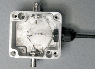
As there is only one output on both of my generators, I made
this splitter to
provide input signals for both the device under test, as well as for the
oscilloscope's reference input. The rudimentary resistive splitter, made
from three 15.9Ω resistors in star configuration, has 6 dB
loss (which means an amplitude ratio of 0.5), and likewise 6 dB
isolation between outputs (so if a significant amount of signal is reflected
from the DUT due to impedance mismatch, part of it may end up in the
reference channel). Yes, the construction is awful, but should be ok for
this low frequency use. With both outputs properly terminated, the SWR was
below 1.5:1 up to 120 MHz—quite bad, but good enough. But feel
free to do this with SMD components on a proper etched PCB, and to add
attenuators to improve matching and isolation, and LNAs to compensate for
loss. And by all means, email me with your design and
results! :)
|
|
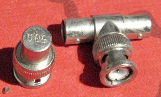
Especially at RF frequencies, you should use 50Ω feedthrough
terminations at the oscilloscope end of the signal cables.
I did not have any in shelf, so I substituted BNC tees and ordinary
terminators (both of which I had accumulated in masses when the Ethernet
networks at my old university were upgraded from 10base2 coax to 10baseT
twisted pair—yes, I'm really that old). I measured the terminators
with my RigExpert AA-1000 antenna analyzer, and
found that they work just fine—the
oscilloscope itself causes a much worse mismatch to 50Ω than the
tee and terminator do! So no need to go overboard with expensive inline
terminations!
If you need a better impedance match, and can afford an attenuation of
20 dB (which corresponds to the 1:10 amplitude ratio found in most
oscilloscope probes), then a 20 dB BNC attenuator should work just fine as
an inline terminator even without any final terminator in place. With
the other end left open, it will present a 51Ω impedance to the
source, corresponding to just 1.02:1 SWR! (The oscilloscope's capacitive
input will make the SWR a tad worse, I think, but still better than the
tee and terminator.)
|
|
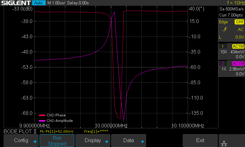
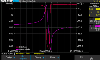
Once I had my program working, I was
eager to see how my Agilent E4421B RF generator plays along with
the Siglent oscilloscope. So even before making the splitter, I hooked up a
10 MHz crystal between the signal generator and the scope's DUT channel,
taking the reference channel directly from the generator. I connected to the
crystal using alligator clips and oscilloscope probes at 1× setting,
with no 50Ω terminations anywhere... Not a proper measurement
setup! But this is the Bode plot
I got—the system definitely works!
|
|
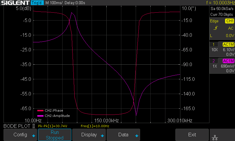
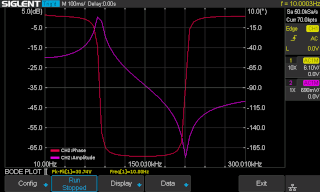
And this is measured using the HP
8904A multifunction synthesizer, feeding into a series LC circuit
comprising a 33 mH inductor and a 1 μF capacitor (also without
any proper terminations, impedance matched splitter, etc...). And it
also works!
(These screenshots, by the way, were obtained over the network with
another simple script
using PyVISA, which I made as a short exercise in Python. I find that much
more convenient than having to plug a USB thumb drive first into the
oscilloscope and then into my PC, just to obtain a screenshot and transfer
it to where I need it.)
|
The program
The program, sds_pyvisa_bode.py,
runs on Python 3.6 and later (as required by the
PyVISA library). It
is distributed under the MIT
License, as it relies heavily on Dmitry's code, which was distributed
under that license.
Since the program binds to privileged ports, it must be run as root.
To test the program, simply run ./sds_pyvisa_bode.py, which will
run it in "dummy mode"—communicating with the oscilloscope
but not with the signal generator. Configure the scope's Bode plot function
source (Utility → Bode Plot II → Config → Source) to
use the LAN interface and the Raspberry Pi's (or whatever computer
you run the program on) IP address. The Bode plot function should now
run happily, but draw garbage. After stopping the Bode plot function, hit
Ctrl+C to exit the program. (I have once seen the oscilloscope hang if I
killed the program while the Bode plot was in progress. Pressing and holding
the power button for some 5 seconds shut down the hung oscilloscope cleanly
enough, but regardless, I think it's better to stop the Bode plot before
ending the program.)
To actually use the program, you must specify the PyVISA resource ID
of the signal generator. The resource ID is a string like
"GPIB0::7::INSTR" (instrument number 7 on
the first GPIB bus, i.e. GPIB0),
"ASRL/dev/ttyUSB0::INSTR" (a serial port
instrument on /dev/ttyUSB0),
"TCPIP::10.42.47.99::INSTR" (an Ethernet connected
instrument at address 10.42.47.99) or something like
"USB0::0x9876::0xABCD::SOMETHING1234::INSTR" (a USBTMC
instrument). You can scan for resource IDs (other than Ethernet) by running
this directly in Python3 with root privileges (ignore all the "Invalid
descriptor" errors):
   >>> import pyvisa
   >>> rm = pyvisa.ResourceManager()
   >>> rm.list_resources()
(See this page for more information on
resource IDs, PyVISA and setting up GPIB on a Raspberry Pi.) Supposing
your RF signal generator is on the GPIB bus with ID 19, you'll start the
program with
./sds_pyvisa_bode.py GPIB0::19::INSTR
This will connect to the generator, report its make and model, set it up
for use, and then wait for commands from the oscilloscope. If something
does not work, you can change the logging level from INFO to DEBUG by
editing the relevant lines in the program immediately after the license
text and import lines.
NOTE: This information is provided as-is without any
guarantees that it will work with your oscilloscope or signal generator.
I'm definitely not an expert on SCPI or Python. But this
kludge did work with my new SDS1104X-E oscilloscope
(software version 6.1.37R8, hardware version 09-06) and my Agilent
E4421B RF generator (middle-aged, obviously, since it's branded
Agilent, not the brand-spanking-new Keysight, nor the
venerable Hewlett-Packard we all used to love) and my HP
8904A (really old, obviously). By all means, do let me know if you
get it working with your hardware, especially if you're using some other
brand or model RF generator! Also, sorry if my Python looks like it's
written with my left foot. I'm a complete newbie in
this. :)
Antti J. Niskanen <uuki@iki.fi>