|
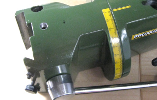
First the drill holder needs to be
disassembled somewhat.
To remove the return spring which pulls the drill upwards, first remove the
screw at its lower end. Then grab the square end of the spring with pliers,
pull it downwards until you have a length of straight steel wire visible,
and tease it out sideways, out of the slot in the moving drill holder (the
yellow part). That part should be a couple of centimeters lower than its
highest position, so there's room for the spring to bend outwards. Once the
lower end of the spring is loose, pry up and remove the knob holding the
spring at the top. It is simply hooked onto the spring. Then remove the spring
entirely. (You can also find youtube videos of how the spring is attached,
for example this
one.)
Finally the black, countersunk Allen screw which holds together the drill
holder and the rack and pinion's toothed bar needs to be removed, as well
as the the plastic height scale indicator / limiter assembly. Now the moving
drill holder will come off, sliding downwards out of the stationary green
assembly.
|

|
I cut a small piece of aluminum
angle profile. Mine was 40×40 mm
in its dimensions, with a material thickness of 3 mm. (I would have
preferred 50×50×5 mm profile, but had none in shelf, and
it's only sold in 2 or 3 meter lengths, if at all. Damn.) I drilled two
4.2 mm holes at one side near the end, about 10 mm apart.
(4.5 mm holes would do just fine, but I had a 4.2 mm bit available,
and thought the tighter tolerance for the M4 screws can't hurt.) Both holes
are countersunk as well on the profile's "outer" side.
But I didn't drill both immediately. I first drilled the one further from
the end. I then bolted the piece onto the movable drill holder (the yellow
part), and drilled the second hole first with a 3.2 mm bit, and all
the way through the drill holder part as well. After removing the angle
piece, I drilled its hole to 4.2 mm as well, and I threaded the new
hole in the drill holder with an M4 tap. I went to all this trouble to ensure
that the holes are the exact same distance apart both in the angle piece
and in the drill holder part.
|

|
Next I drilled a 5 mm hole at
the top side of the green assembly. I
then threaded it with an M6 tap. I put the hole along the centerline of the
assembly, quite close to the front. This place is not ideal, as the future
adjustment screw will only have some 20 mm of downwards travel before
it hits the rack and pinion's gear. You could get a longer length of travel
if you locate the hole further back, beyond the gear. This will, however,
require a longer horizontal length for the angle piece (I doubt even the
50×50 mm profile would reach far enough), and it will also put
quite a bit of torque on it—I'm not at all sure it would have worked
very smoothly!
You can now clean up and re-assemble the entire assembly, though you might
not want to re-attach the spring just yet. But while it's still open, why not
grease up the moving parts of the rack and pinion.
You might also check the condition of the sliding dovetail
surfaces, perhaps smooth them out with fine sandpaper, and goop them up as
well with good quality grease. That will make it move a lot more
smoothly!
|

|
To go into that M6 threaded hole, I made a
thumb screw out an M6 bolt and
a piece of 20 mm diameter Nylon rod.
With the help of my dividing head, I marked ten divisions
on it, like there are on the hand wheels of the compound table.
Just like those, the
M6 height adjustment screw also has a travel of 1 mm per revolution.
I engraved the divisions in the knob's top surface and sides, and also
dragged a thin black marker along the grooves. I drilled a hole through its
center, and made a recess below the surface level for the bolt's head. I
ground the head into a flattish shape, and made the recess similarly
flat, so the knob cannot spin freely on the bolt. I attached it onto the bolt
with a washer and a lock nut.
I placed a couple of additional lock nuts at
strategically selected positions. Their purpose will become clear soon.
Oh, man, this thumb screw is ugly! :)
|

|
I drilled a 6.5 mm hole in the angle part's top side, at a position that
will line up with the M6 threaded hole I made, when the angle piece is
installed. I then cut the angle piece to length,
and made a slot from the hole to the edge, as shown
here.
I used a hack saw to make a rough cut, and then milled it more nicely
with the Proxxon. The thumb screw fits into the slot
as shown in this photo.
There's a bit of sideways play, which is intentional, but I adjusted the
lock nuts so that the screw just turns freely, but with hardly any play
along its axis, i.e. in the vertical direction which it will be
adjusting.
Finally I attached the angle piece onto the drill holder.
I used two countersunk M6×16
screws, one of which was the perfect length for the upper screw (which
reaches all the way through the angle piece, the (yellow) moving drill
holder piece, and screws into the threaded hole in the rack and pinion's
toothed bar. The other one had to be cut to length some 5 mm shorter.
Both will be affected by how far the holes in the angle piece are countersunk.
I wasn't clever enough to countersink just the right amount to use the
original screw here.
|

|
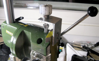
Here's the angle
piece and adjustment
screw in place. The screw can be attached and removed easily,
since the angle piece has a slot for it, rather than just a hole.
When attaching the screw, first bring the drill holder down to
a suitable height, and insert the bolt into the angle piece's slot
between your choice of
lock nuts. This coarse adjustment helps mitigate the limitation
of only having about 20 mm travel adjustable by the screw. The
lower-most lock nut limits how far the screw can go, so it just does not
touch the rack and pinion's gear.
Once this was in place and tested, I re-attached the spring, and was
done! If you will only ever use the drill stand for milling
and will only ever adjust the bit height with this new thumb screw, you can
even leave the spring out.
|
The verdict? Ugly as hell, but it works!
And it is a lot more precise than trying to read off
millimeters from the awful depth scale. One revolution is exactly one
millimeter, and that's it. I did not bother to put any kind of pointer
to indicate the divisions marked on the knob—I generally just
eyeball a number at a suitable direction and rotate away. I don't
expect this mechanism to be that precise anyway!
There is a bit of play, in fact,
but unlike the axes of the compound table, the height adjustment is spring
loaded, so most of the time even that bit of play is all but removed.
But it's still a good idea to tighten the original
locking screw on the height axis before starting to mill anything.


