|
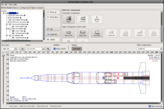
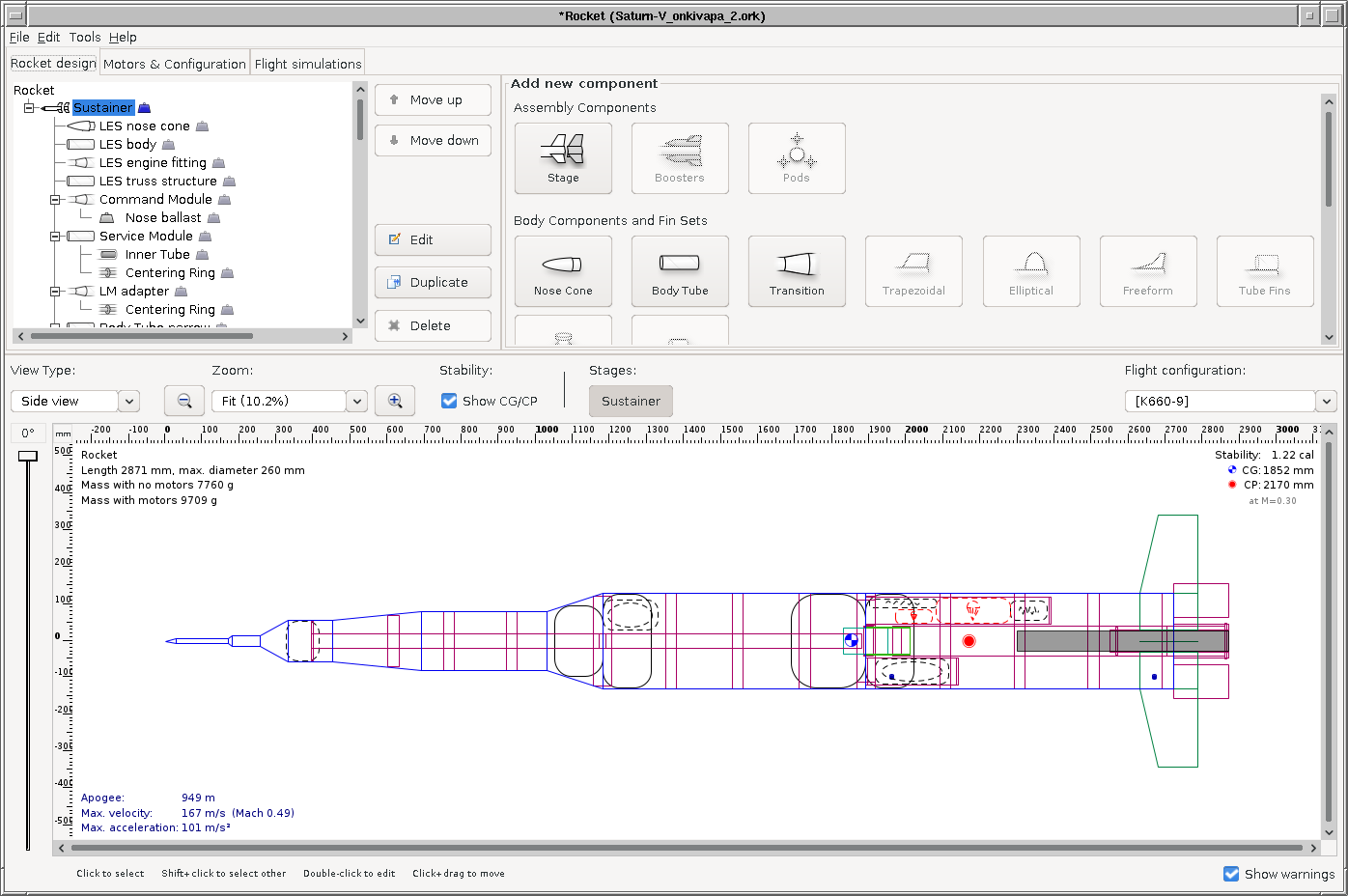
The design: I always begin by modelling my design in
OpenRocket. I start with the crude
design, with approximate values for sizes and weights, and tinker with
options for motors and construction materials. This phase is just to see
if anything I'm considering is actually realistic, or if I have to change
my approach, materials, motor choice etc. entirely.
I was initially planning to use
cardboard tubes
intended for casting concrete pillars (also known as "sonotube")
as the body of the rocket. I soon found out that they're way,
way too heavy. To make the rocket stable in flight, I'd either need
to make the tail fins much too big (not so great for a scale model), or I'd
need a ridiculous amount of ballast in the nose cone! So scratch
that, and go with a light-weight fiberglass composite skin, over a
load-bearing inner structure made of fiberglass fishing rod
segments—way strong in lengthwise compression, and also light-weight.
I even went with light-weight fiberglass composites for the tail fins, instead
of the simpler but heavier plywood, to further reduce the ballast required.
As I worked on my design choices, and as I eventually began gathering and
building the flight hardware, I kept updating the OpenRocket model to keep
myself up-to-date on how the rocket's performance looks, regarding
stability and apogee. Here is the final model:
saturn-v.ork.
|
|
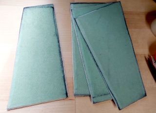
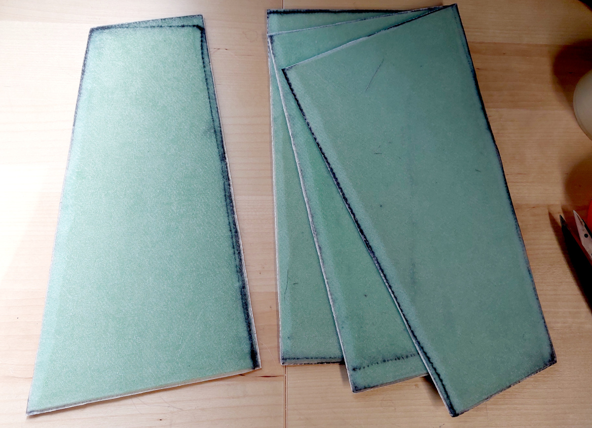
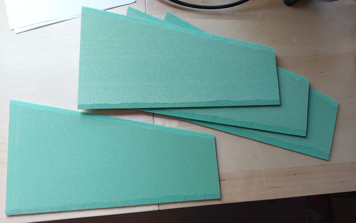
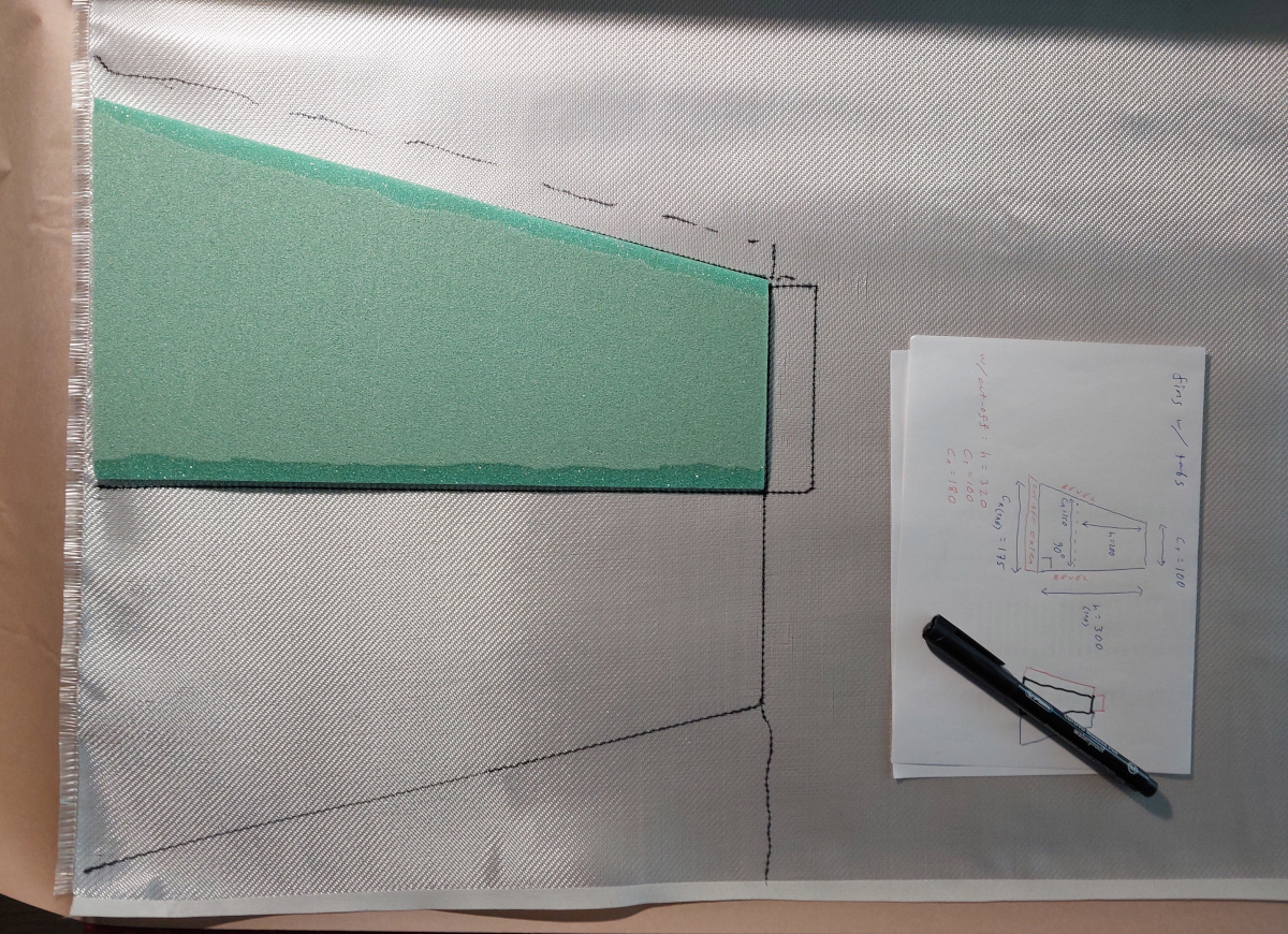
The tail fins: The tail fins are fiberglass composite.
I used a core
of 5 mm thick EasyCell75 Closed Cell PVC Foam, which I laminated
twice with 160 g/m2 fiberglass 2/2 twill fabric and
EL2 Epoxy Laminating Resin using the slow hardener. The materials
came from Kevra and
EasyComposites.
I cut the foam cores of the fins
with a utility knife and beveled their
leading and trailing edges. I
drew outlines onto the fiberglass
fabric, and cut them with extra fabric all around. For the first
laminating layer, I added a flap to turn around the tip of the fin, and
turned the fabric around the trailing edge of the fin, leaving the leading
edge "open" (although the extra fabric going past the edge does
close that edge pretty well). I placed the fabric over the core, and
applied the epoxy with a cheap paint brush.
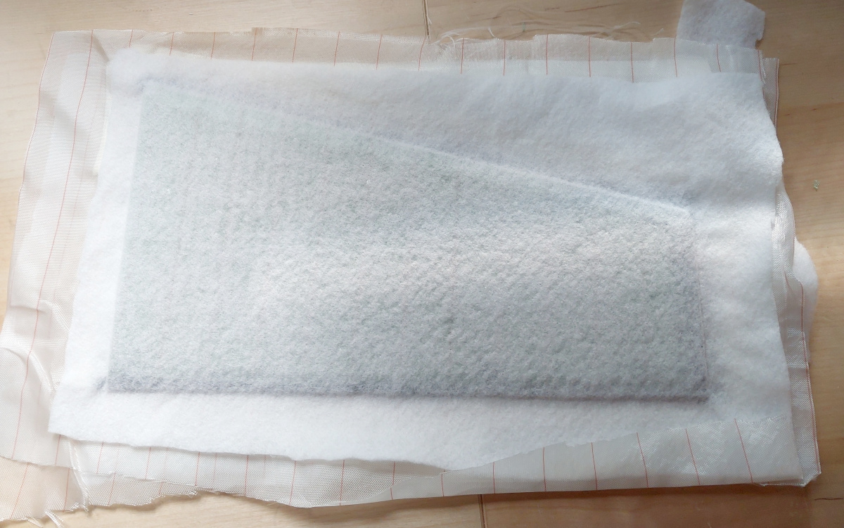
I laid release fabric
("peel ply") and absorbent fabric
("breather/soaker/bleeder cloth") on both sides of the fin,
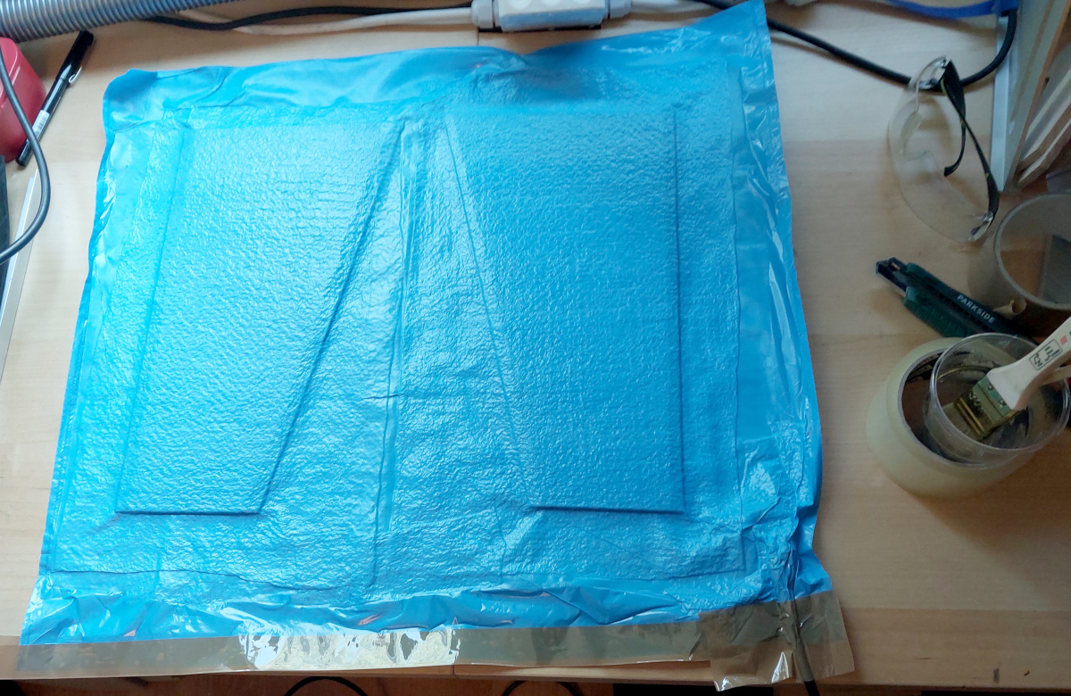
and enclosed two such
sandwiches in a plastic
garbage bag, which I taped up with a vacuum
hose inside. I pulled in a vacuum with my
Reciprotor vacuum pump,
which I left running until the epoxy was properly set (as evaluated by
prodding some leftover epoxy in its cup, something like
8–10 hours). The next day I tore open the vacuum bag, tore
away the release fabrics, and trimmed the edges of the fins.
For the second layer, I simply turned the fabric around the forward edge,
and let all other edges be as they are. After repeating enough times, I
had four strong but lightweight
fins.
The process is essentially the same as
the carbon fiber process that I used in
the construction of one of my telescopes, except
here I first laid the fabric over the core, and then painted on the epoxy,
rather than first gooping up the fabric with epoxy, and then laying it over
the core. The latter is easier for bulky objects, whereas these fins were
mostly flat.
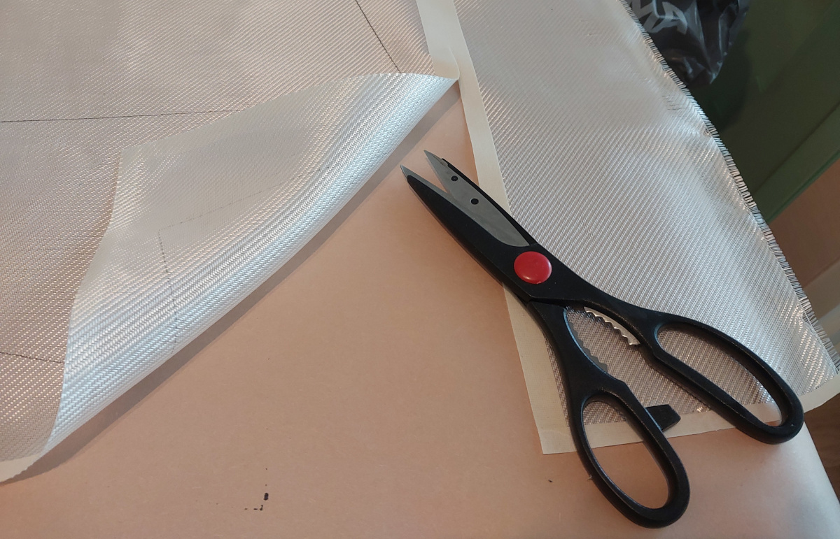
Pro tip: As long as it doesn't hinder your process
(i.e. if you leave extra fabric all around, which you will
trim away afterwards), lay a strip of masking tape over the fabric,
and then cut along that.
This will keep the fiberglass strands from
separating, and you'll end up with straight cuts and a lot less mess!
|

|
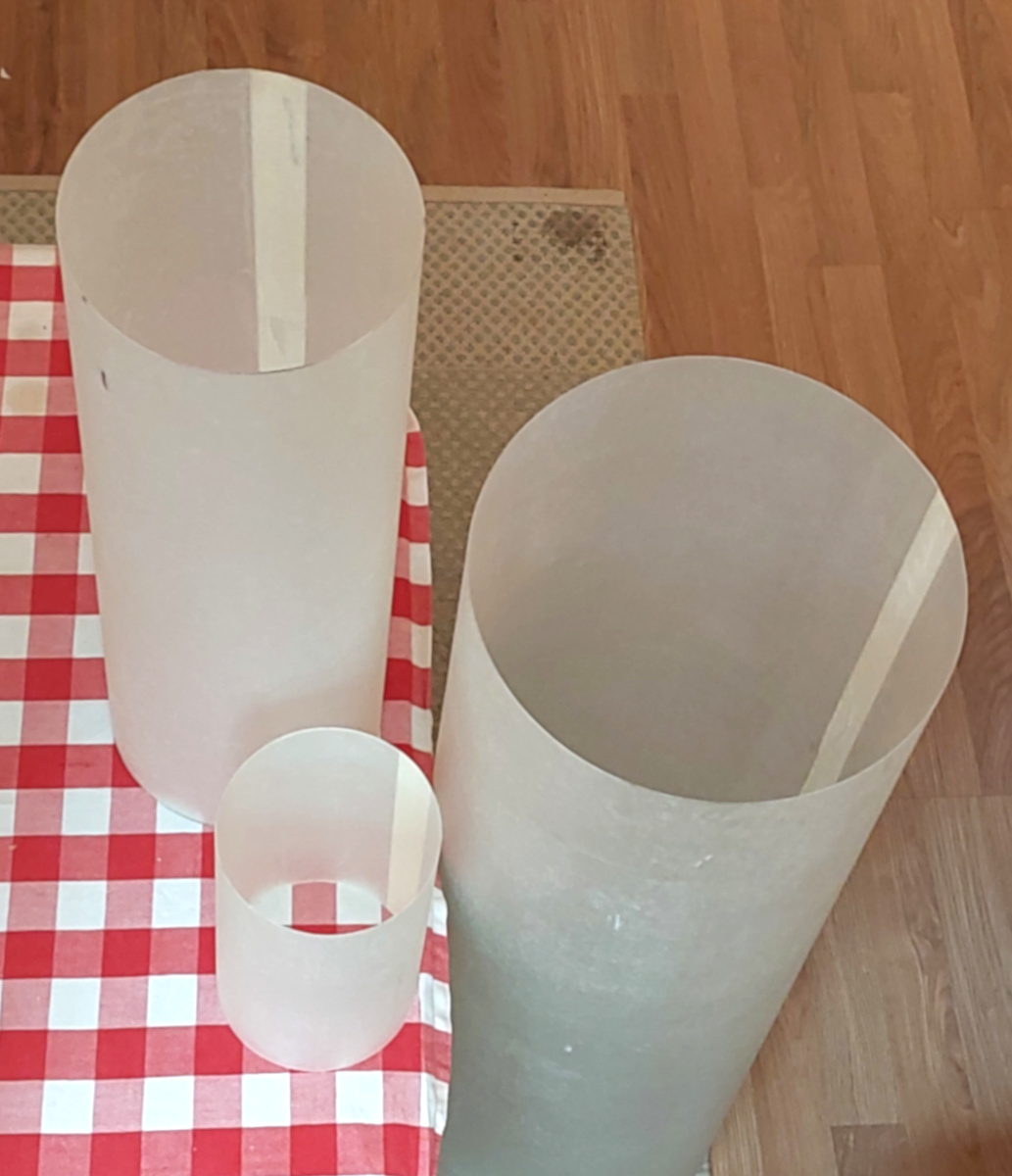
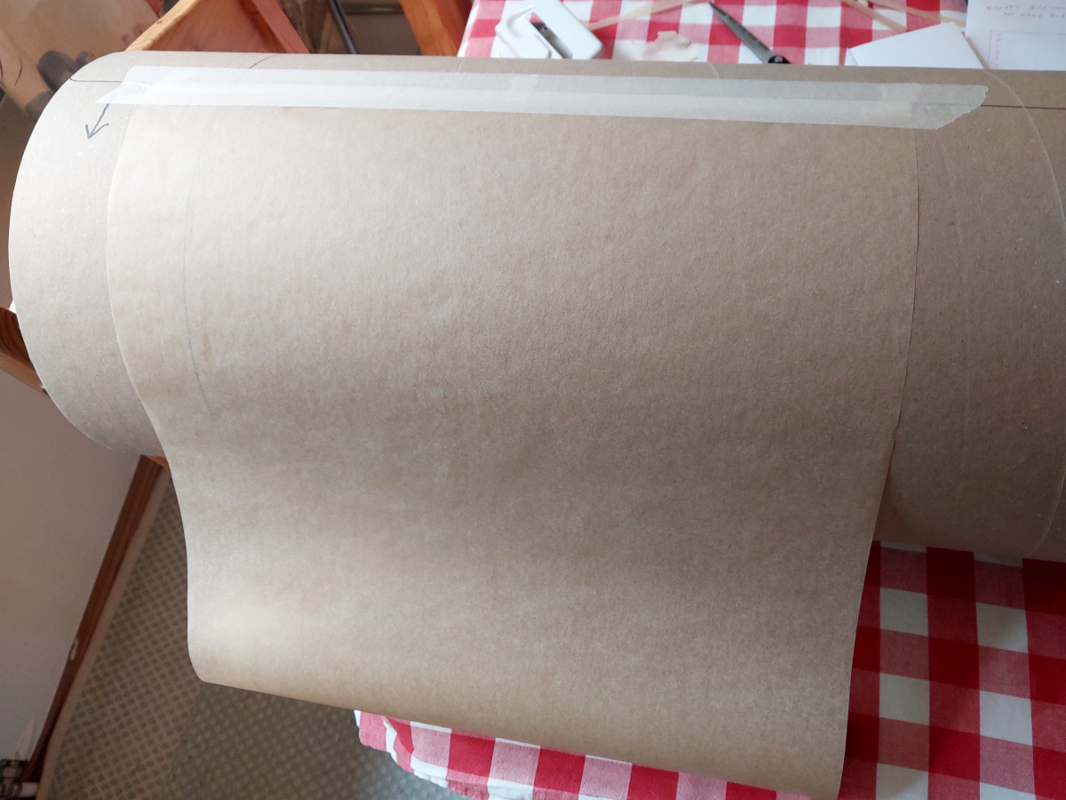
The exterior body tubes: These are not intended to be
load-bearing.
I used cardboard tubes
meant for pouring concrete (i.e.
"sonotubes") as forms. I
wrapped baking parchment
around them, to keep the fiberglass laminate from sticking to the cardboard.
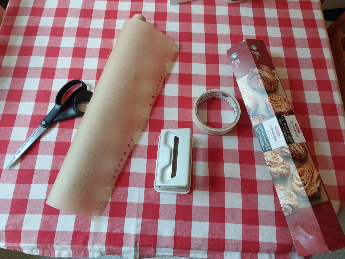
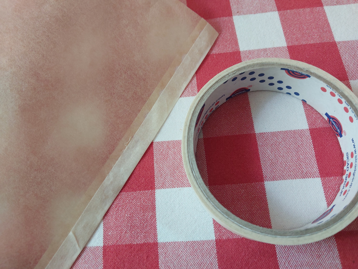
Nothing will stick to baking parchment, so I had to
perforate all along
its edge with a paper punch, and then
tape over the perforated
edge, before I could secure it to the form.
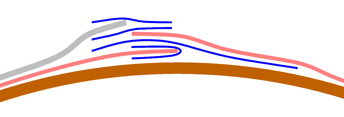
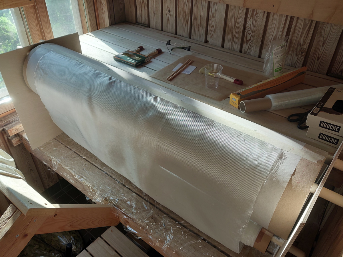
See this diagram how I wrapped
and secured the parchment (pink) with masking tape (blue) of two different
widths around the cardboard tube (brown),
and finally attached the leading edge of the fiberglass fabric
(gray).
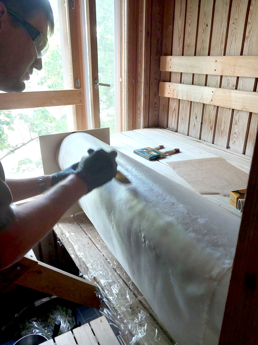
I made a jig out of plywood and broom handles to
hold the form and the roll
of fiberglass fabric.
I then began applying epoxy
with a paint brush, rotating
the form as I progressed. I laid three layers of 100 g/m2
fiberglass cloth in total, and finally placed a layer of baking parchment
on the outer surface so make it nice and smooth.
Once the epoxy had set, I peeled away the outer parchment layer, and then
demolished the cardboard tube by brute force from the inside. A strip of
masking tape remains along the length of the tube, where it was exposed to
the epoxy—that is unintentional, but not harmful in any way. There's
also a very slight bulge in the tube along that tape line, but if suitably
placed relative to the paint job and other trinkets, it could be all but
invisible.
The resulting fiberglass
material can be cut with scissors (just use cheap ones, not your
best ones). A tube
1 m long by 260 mm diameter weighs only 480 g,
whereas the original cardboard tube weighed 2.6 kg!
|
|
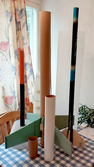
The internal load-bearing structure: I bought two 8 m long
telescoping fishing poles, which I disassembled. The thickest lower
segments were used as the internal structure of the Saturn-V.
The rocket is designed to split into two parts during flight, when the
motor's ejection charge goes off. The lower part contains the motor
mount, fins and main parachute compartment.
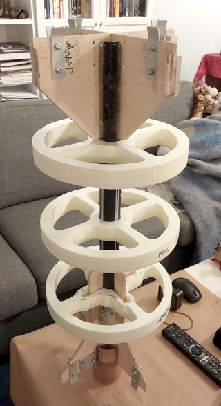
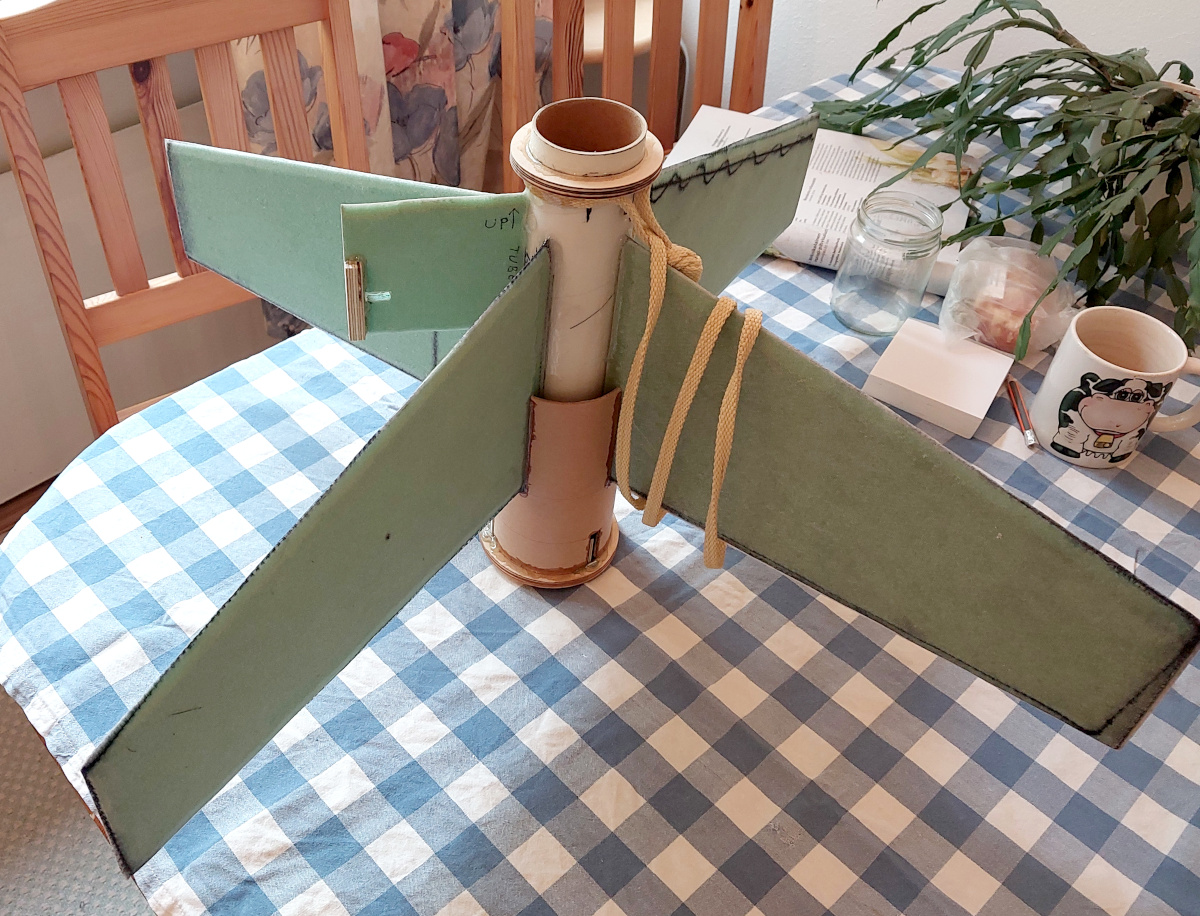
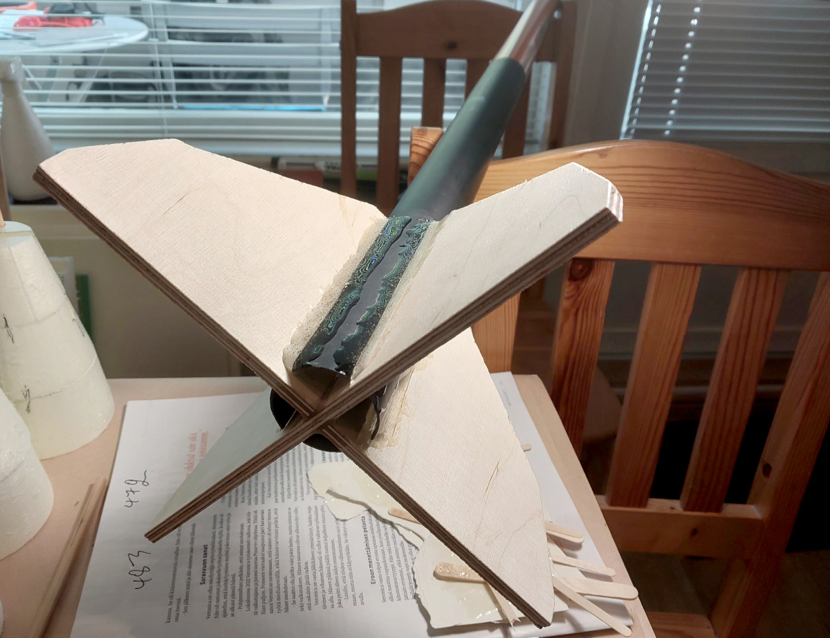
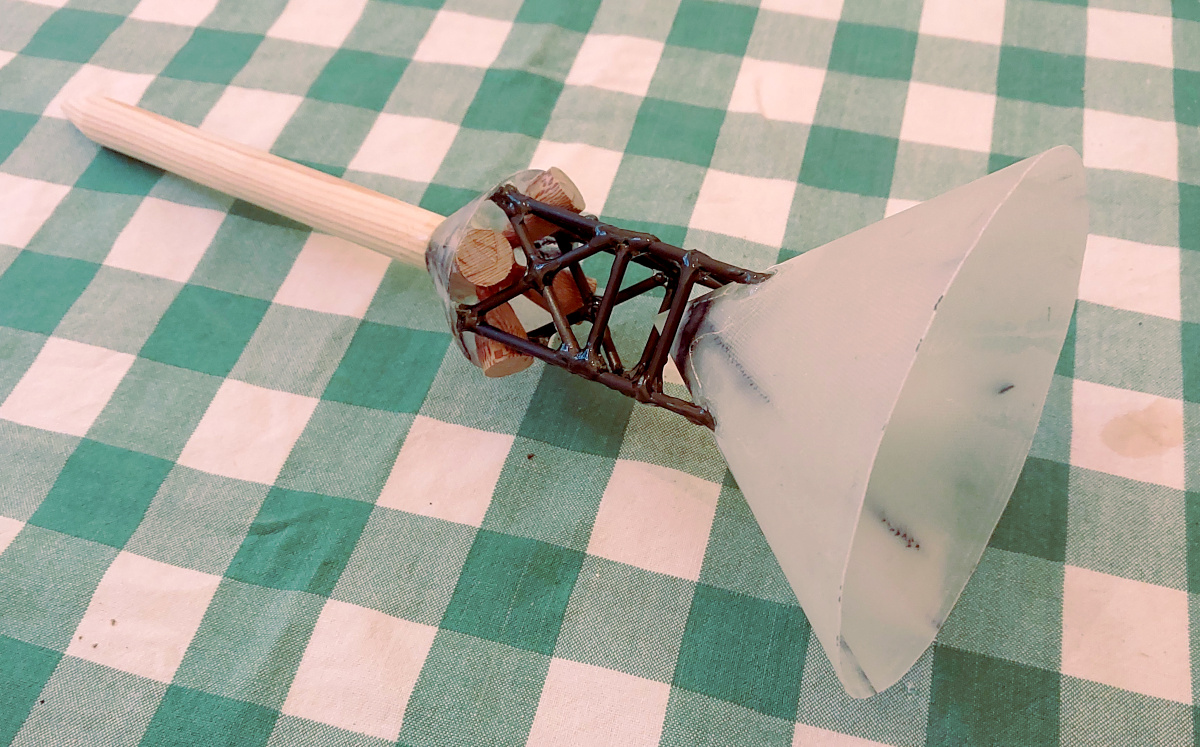
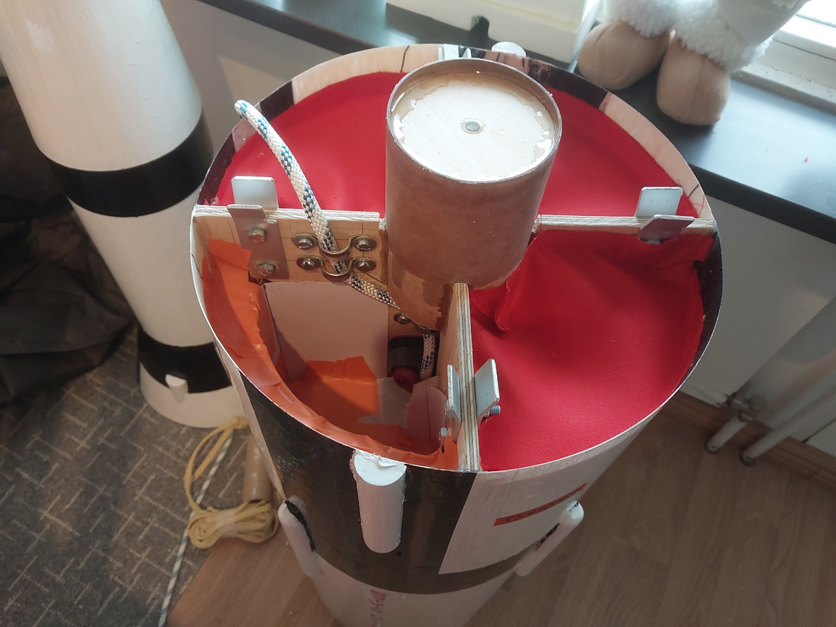
The upper part is much longer,
and it is designed to separate into two parts for transportation.
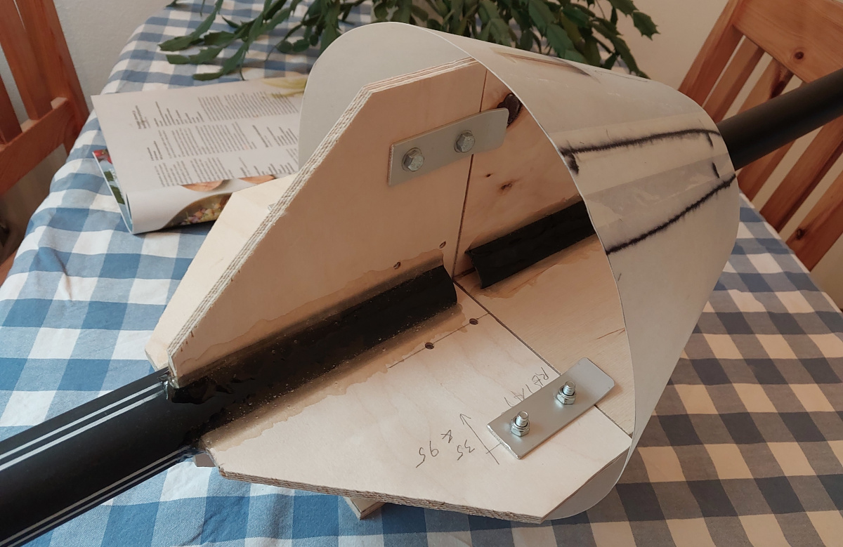
Those two parts have the fishing pole tubes as their cores. There's
crossed triangle structures
epoxied to the ends of the fishing pole tubes,
which keep the two parts in line. (They also support the outer fiberglass
skin, which is why they're so large.)
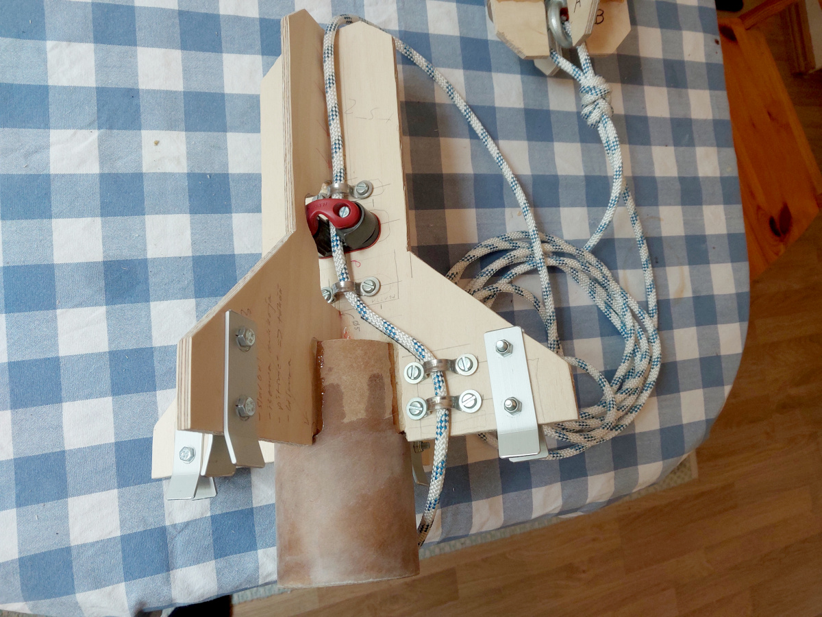
Small flaps of aluminum
keep the plywood triangles aligned with each other (in this photo, one
conical section of the outer skin is already attached to the supporting
structure).
A sailing rope
comes from the nose ballast, down through the
upper fishing pole tube, then down through the lower fishing pole tube,
which has a Harken H468 cam cleat at its bottom end. My original idea was
that at the launch site, I'll unpack the rocket, assemble the two upper
segments, and simply tighten that Kevlar rope as tight as I can make it by
hand. This would make the upper two segments into one, and they could easily
be separated again after flight! However, once I had loaded up the nose
ballast, I found out I couldn't hand tighten the rope enough to make the
structure rigid—it always flexed and wobbled at the joint. So at the
last moment, I made a panic addition of four nuts and bolts at that joint,
which left the cam cleat redundant. Ironically, the yank at parachute
deployment was so hard, that after the flight the joint was absolutely
solid even with the bolts removed! In fact, I couldn't even release the rope
from the cleat without tools!
The lower part of the rocket is built around the motor tube, a sturdy
cardboard postage tube (in fact, the fiberglass fabric I had ordered came
wrapped around this tube), and a length of commercial 75 mm
rocket body tube made by Klima,
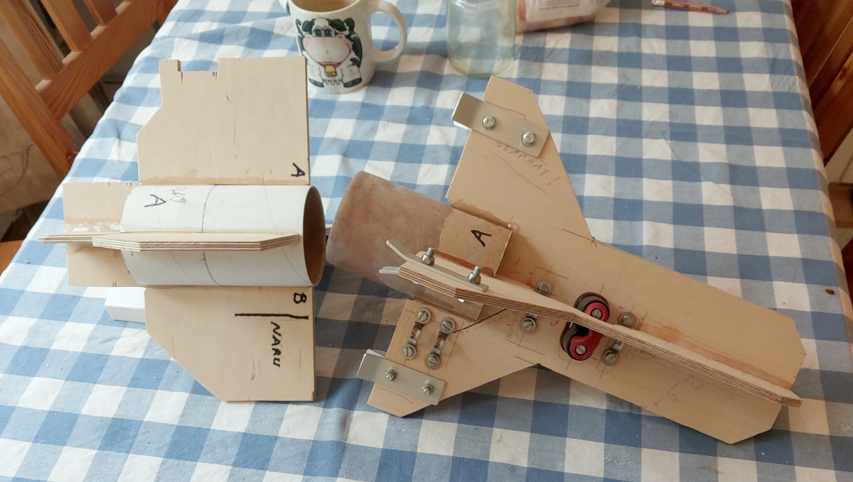
for which I had suitable couplers as well. You can see
one side of the coupler in the
the earlier photo.
Here's a picture of both sides of the
coupler.
The same sailing rope, coming down through the upper two segments, is part
of the recovery harness. I used sailing rope, because the cleat grabs it
better than Kevlar. Since it goes directly all the way up to the nose
ballast, it
minimizes the stresses on all other structures at parachute deployment.
In the lower part of the rocket, I did use Kevlar, even
though it's not even exposed to the ejection charge, since it and the parachute
are packed into a side compartment, not in the motor tube itself. It goes
all the way down to the
motor mount, where it is tied and expoxied in
place behind a centering ring.
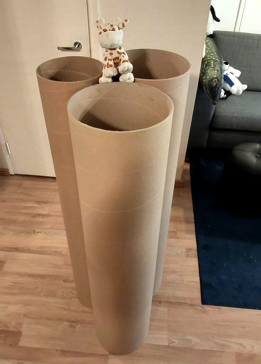
Here's a picture of the
load-bearing interior tubes
side by side. The white tube at the front is a 75 mm body tube which
will become the parachute compartment.
|

|
The motor mount: The motor tube is a commercial 54 mm motor
tube by LOC Precision / Public Missiles Ltd. It is
reinforced with two layers of 160 g/m2 fiberglass, since
the fins are epoxied to it—the epoxy can withstand pretty much any
violence, but the cardboard of the motor tube itself might be torn up in an
impact. At its upper end there's
a plywood centering ring, which attaches it to a sturdy postage
tube. The bottom end of the motor tube also has a centering ring,
fitted with impact nuts to serve as the motor retention system. It
extends somewhat beyond the lower edge of the fins, so a separate piece of
the same postage tube attaches from that direction.
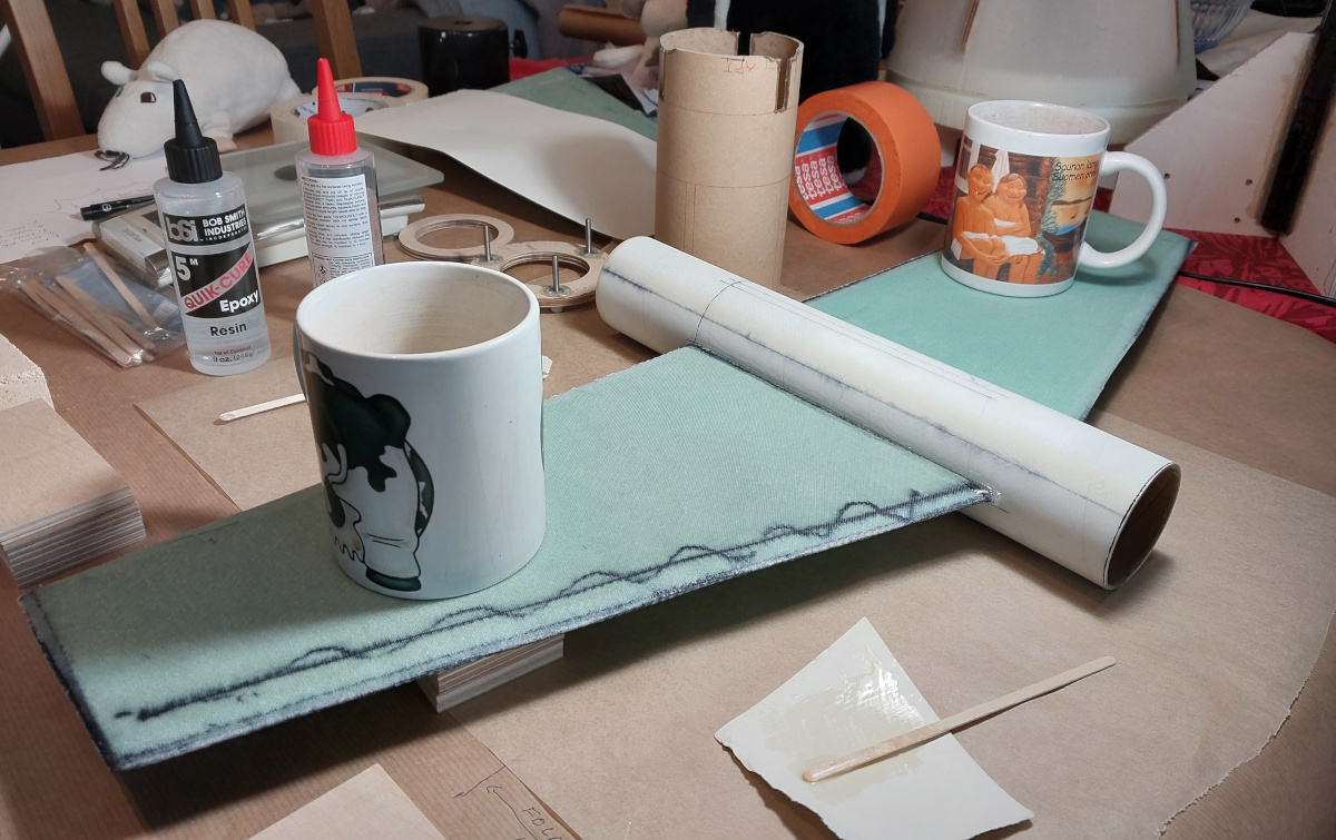
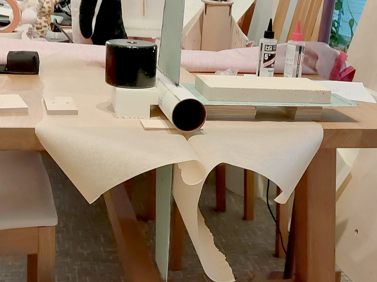
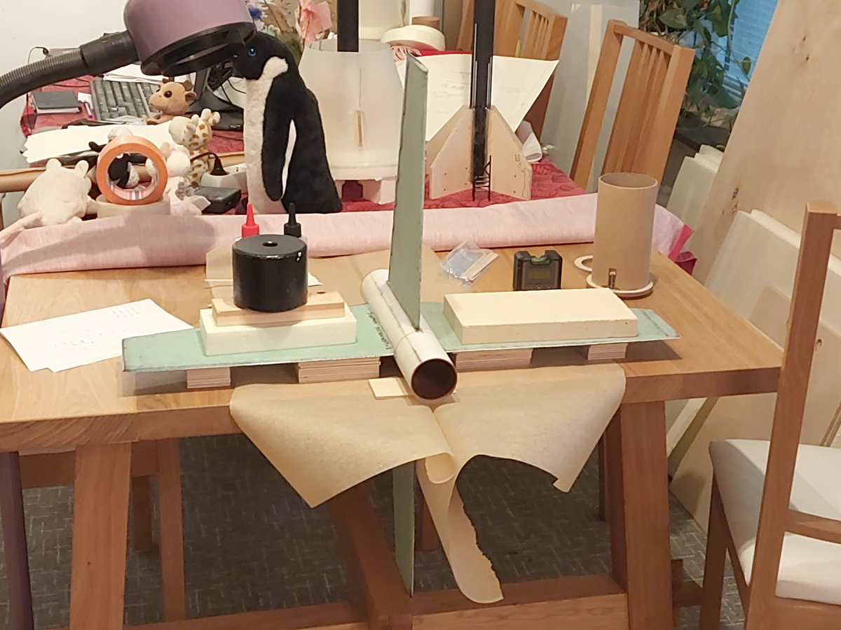
The fins are epoxied onto the motor tube. Here's
the first one going on, with
a suitable stack of plywood pieces underneath to keep it square against
the motor tube. Here's
the second one, supported
by the same thickness stack of plywood. The coffee mugs only serve as
weights while the epoxy cures. Here's
the third one going on. Now the
two first fins need to be vertical. By incredible good fortune, the Ikea
dinner table in our living room is composed of two separate slabs of wood,
with a slot between them—and the lower one of the vertical fins just
fits into that slot! I used a digital bubble level to ensure that they're
off-vertical by exactly the same amount the third fin is off-horizontal.
And finally here's the fourth one.
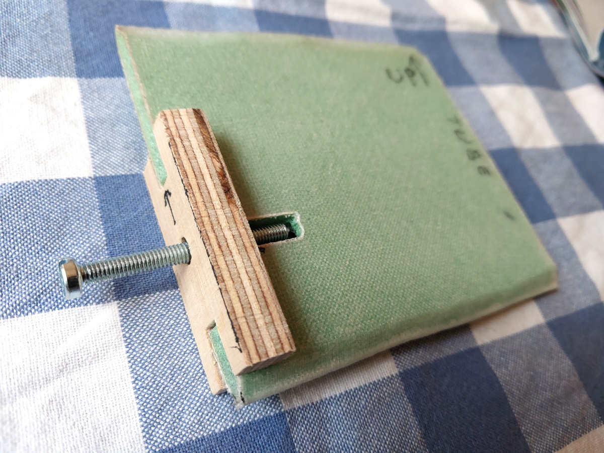
In addition to the fins, I made a
fiberglass composite flap
that will
support the lower launch lug, which couldn't be supported by the rocket's
flimsy outer skin only. (The upper lug was supported by one of the coupler
triangles.) Here's the
complete motor tube with fins, centering rings, Kevlar
harness and all. The small lower piece of postage tube is also in place.
And in this photo the
upper part of the tube is also in place. The fins are, of
course, filleted to that tube as well. There's a hole in the postage tube
through which the Kevlar harness comes to the outside of the postage tube.
That hole is below the motor tube's upper centering ring, so it does not
vent ejection charge gases onto the outside of the tube.
|
|
Support for the skin: With a take-off acceleration of
some 10 g or so (that was my initial working figure, but the rocket
gained a lot of weight and lost a lot of gees after that), the half kilo
of skin in a single rocket segment momentarily weighs
around five kilos—not all that much. It is attached to the plywood
triangles at the ends of each body segment, with epoxy and hefty fillets.
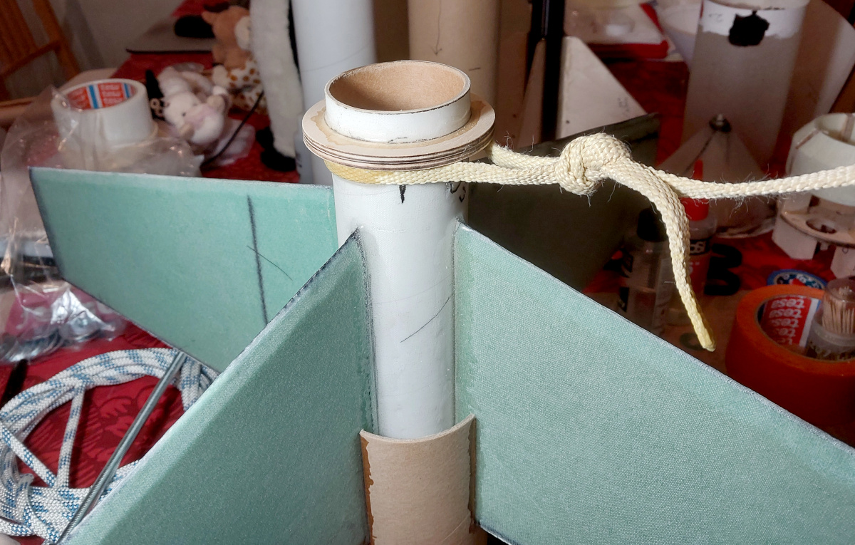
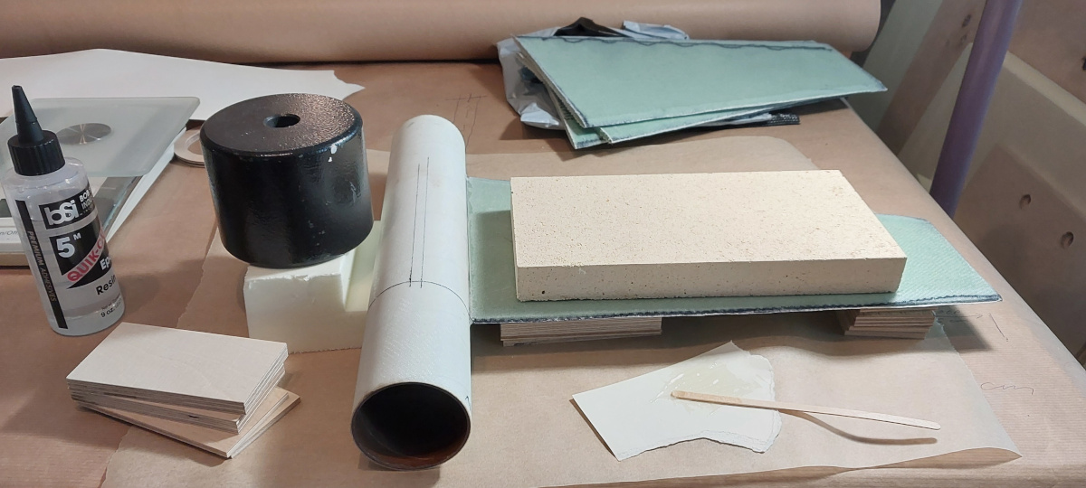
Along the length of the tube, there are only
centering rings made
of "Finnfoam" XPS insulation foam. I used a thickness of 30 mm
for simple centering rings, and 50 mm for couplers between the three
segments of the rocket, as well as the decorative dummy engines surrounding
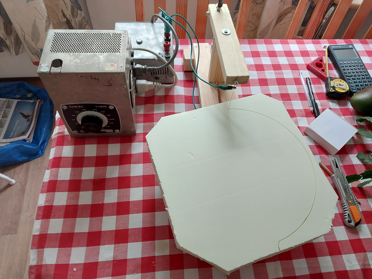
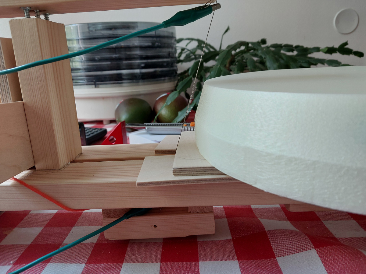
the central rocket motor. I cut the
centering rings using my DIY hot wire. It is
easily adapted even to cut
beveled supports for
conical parts of the rocket.
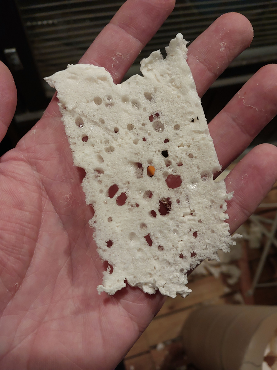
Even with a centering ring every 20 cm or so along the
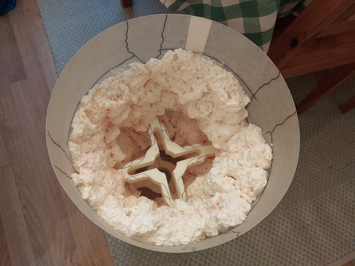
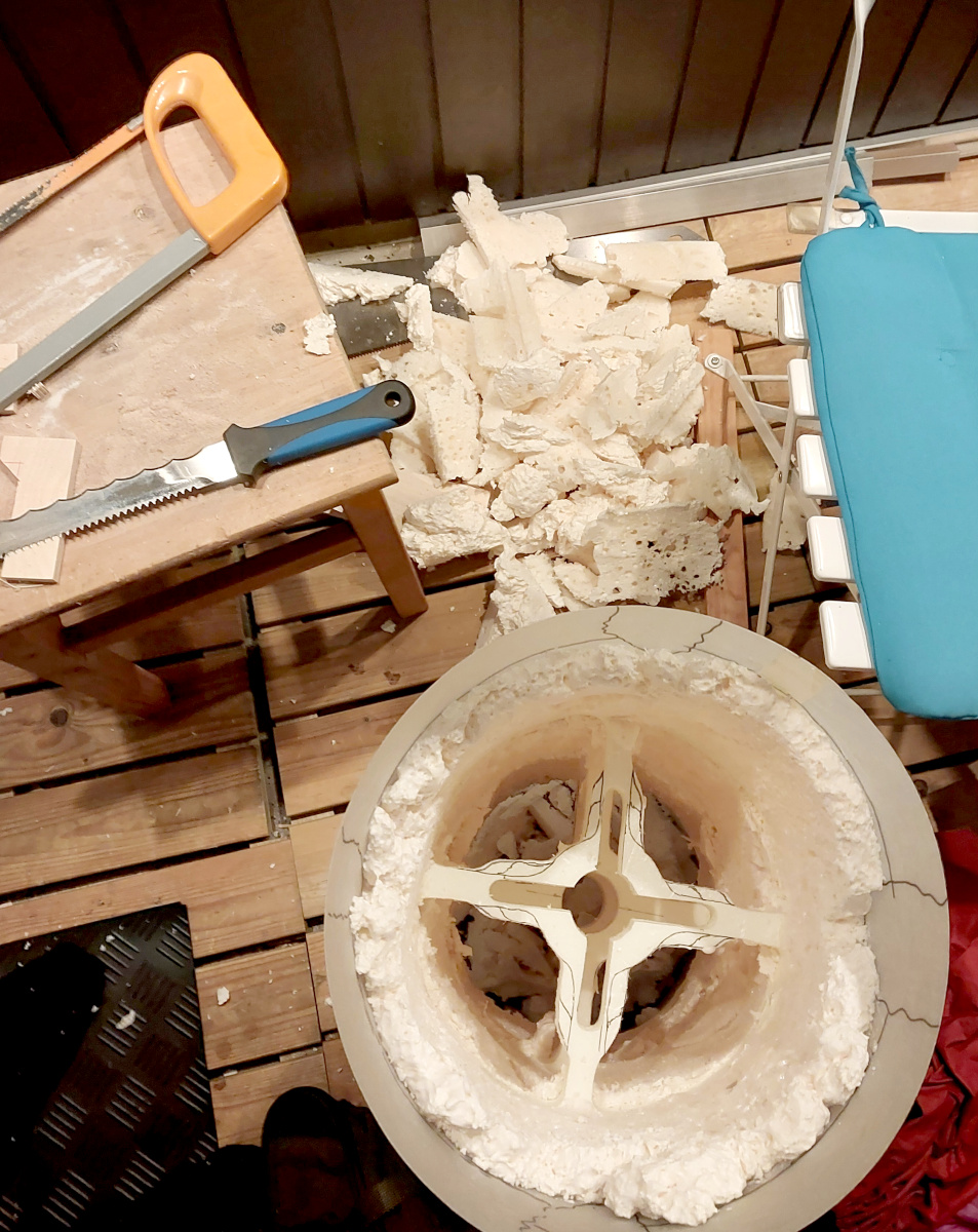
rocket's length, the skin feels... flabby. So, after gluing the rings into
place, I squirted
a layer of polyurethane foam
onto the inner surface of the skin. This stuff cures into a
relatively hard mass, giving the skin a more firm feel. I then cut it to
a more uniform thickness
of an attoparsec or so. Cut-away slices of the stuff
look just like cheese!
This does add a few hundred grams of
mass, but no matter. Now the rocket's skin doesn't actually buckle when
the rocket is handled.
|

|
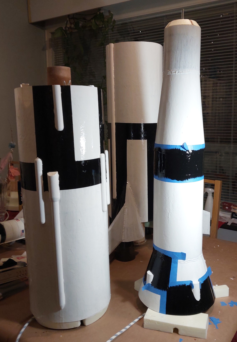
The aft end of the rocket: The motor's thrust is directed to the
cardboard postage tube, and from there to the upper parts of the rocket.
By sitting on the end of the tube I verified it can take the forces
involved. The fins are epoxied and filletted to the motor mount and the
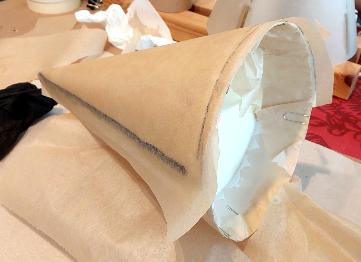
postage tube, as well as the outer skin. Finally, the fins poke through
the Saturn's iconic engine
fairings, which I
laminated out of a couple of
layers of fiberglass over a conical cardboard form, whose shape I derived
mathematically, drew onto cardboard, cut out, and glued into shape over
beveled discs of Finnfoam. No, I won't deprive you the pleasure of deriving
the shape yourself. (I did the same for other conical sections of the rocket,
i.e. the nose cone and the interstage and LEM storage bay fairings.)
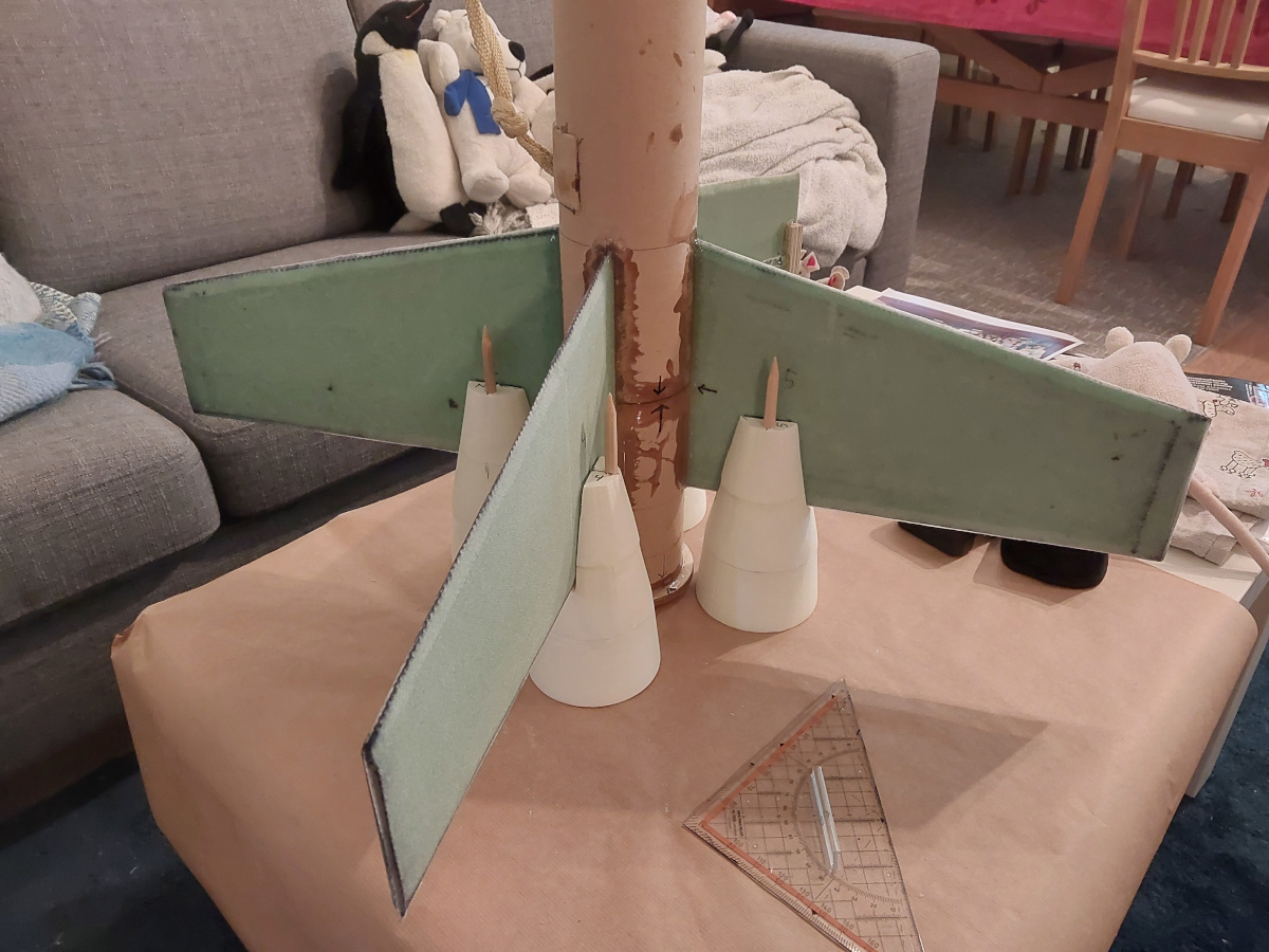
There's only a single, central motor mount in this rocket. No, I don't think
I'll be launching this on a five-strong cluster of HPR motors. So surrounding
the actual motor there are four
"dummy" engines
cut from Finnfoam
and glued together, with support structures made of wooden chopsticks. These
dummies are glued to the fins and to the Finnfoam bottom end plate of the
rocket.
You may notice the fins are just a tad large when compared to the original.
That is an intentional design choice. To make the rocket stable, I could
either make the fins bigger (which is not a faithful scale model), or I could
add an unreasonable amount of nose ballast (not that good an option either).
So I compromised, and did both to a degree. At first glance, the fins aren't
grotesquely oversize, and just a kilo of nose ballast didn't cost hundreds
of meters in apogee either.
|
|
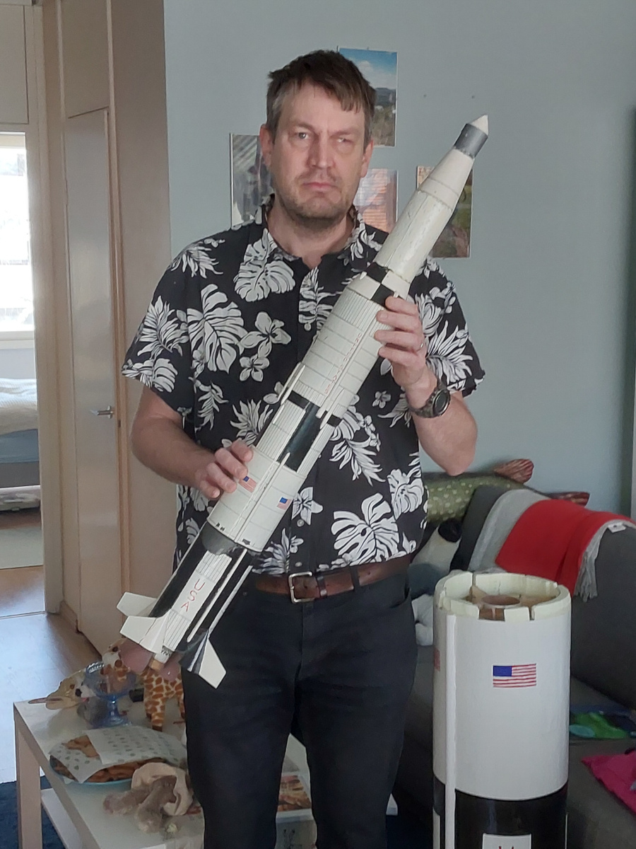
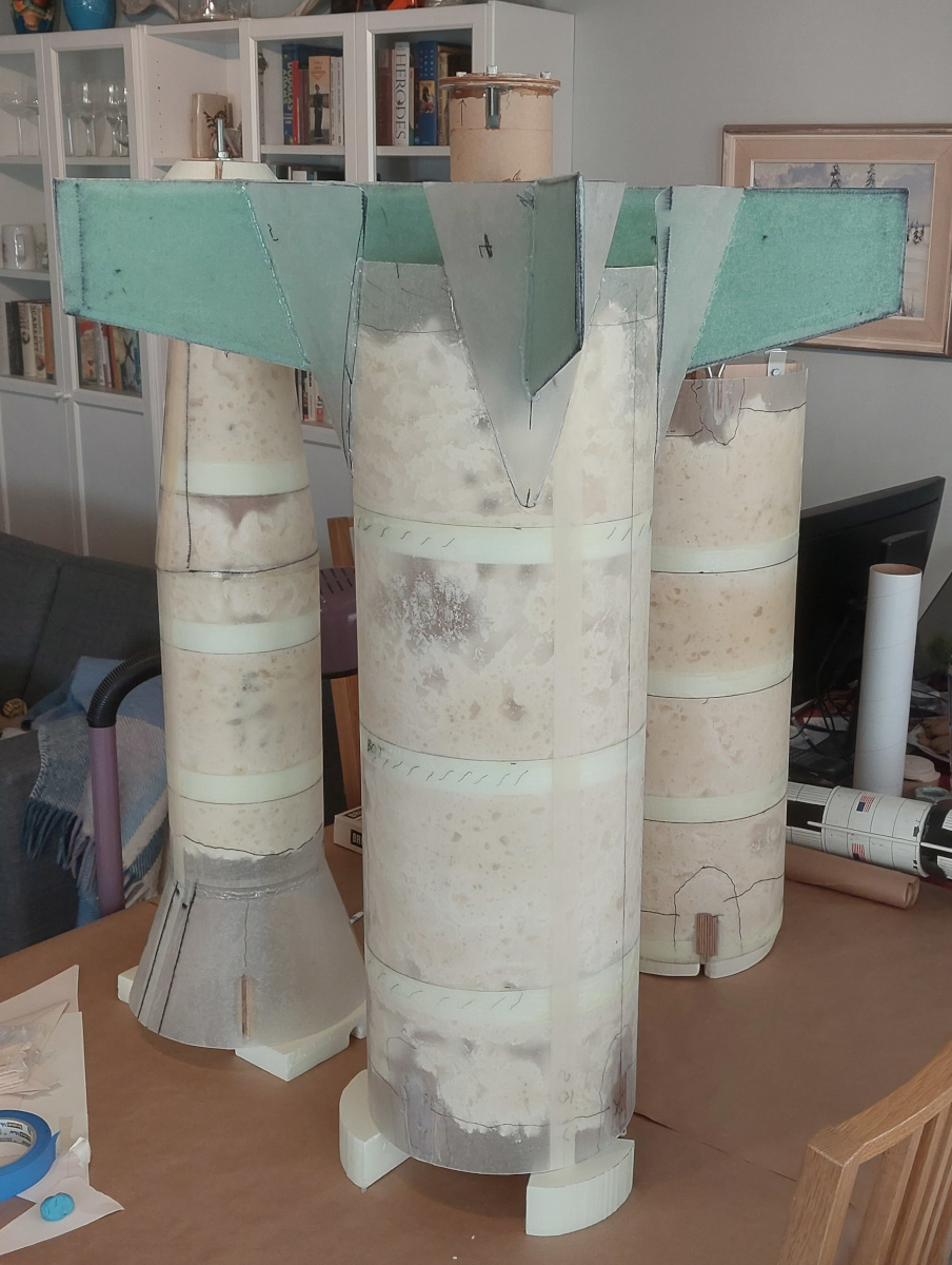
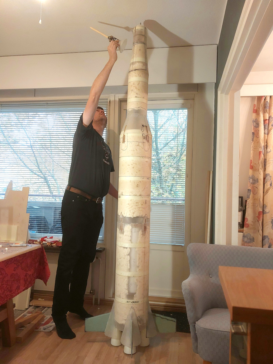
The nose cone and ballast: As said, I needed a decent
amount of nose ballast
in order to keep the fins from being grotesquely oversize. I designed
the nose of the rocket
(i.e. the service module and the crew capsule) so that
I can add the required amount of ballast once everything else is ready and
I can check the true center of gravity by
balancing the rocket. (The service
module section of fiberglass exterior tube has not yet been cut to length,
and you'll notice I've used it for testing the paints I'll be using.)
The sailing rope that goes through the entire upper section is
connected directly to the
bolt that holds the ballast weights, so no matter how heavy they are, they
won't try to rip the rocket apart when the recovery deployment charge
fires.
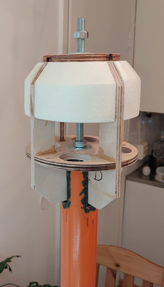
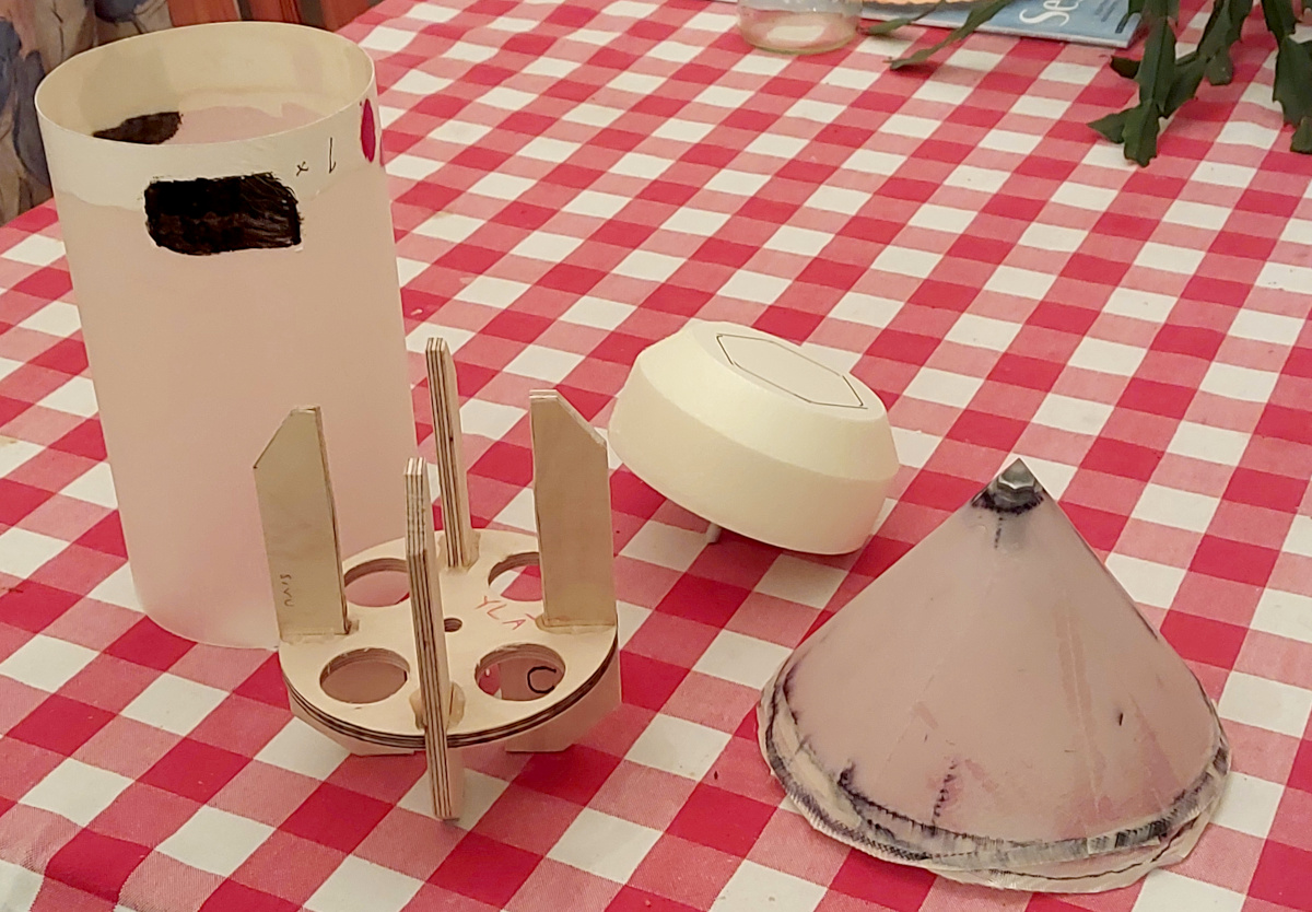
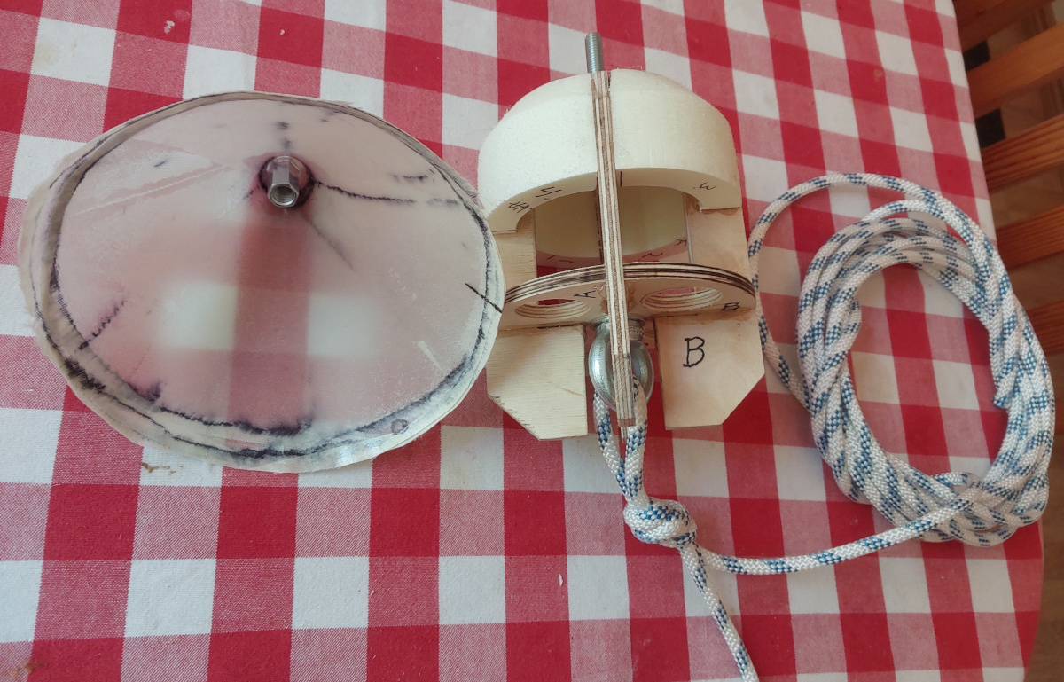
The nose of the rocket, ballast and all, is epoxied to the
top of the supporting
structure—one of the fishing pole segments.
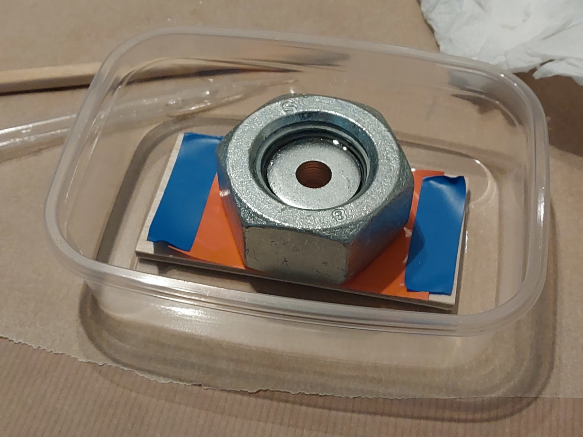
The ballast itself comprises the
biggest possible nuts that will fit inside the structure, with a
stack of washers within the nut, and the empty spaces filled with epoxy. A
hole is finally drilled in the epoxy through the washers' central holes. This
can be inserted onto the central threaded rod of the nose cone structure, and
secured with a nut. I eventually needed two of these ballast weights, which are
just under 500 grams each.
Note that the conical part of the nose cone itself can be screwed onto and
removed from the central threaded rod. That is intended to allow passage
inside the structure, to add or remove ballast weights. And the Saturn's
iconic Launch Escape System
is part of that nose cone. While assembling the entire rocket the first time,
I ran out of room trying
to install the nose cone and LES! Regrettably,
after prepping the rocket on
the big day, I accidentally slammed the LES against the tailgate of the van
that drove us to the launch site, and broke it clean off. Oh well, I never
expected the LES to survive landing at any rate, and it was not critical in
any respect. But that's why you don't see it in any of the launch photos.
|
|
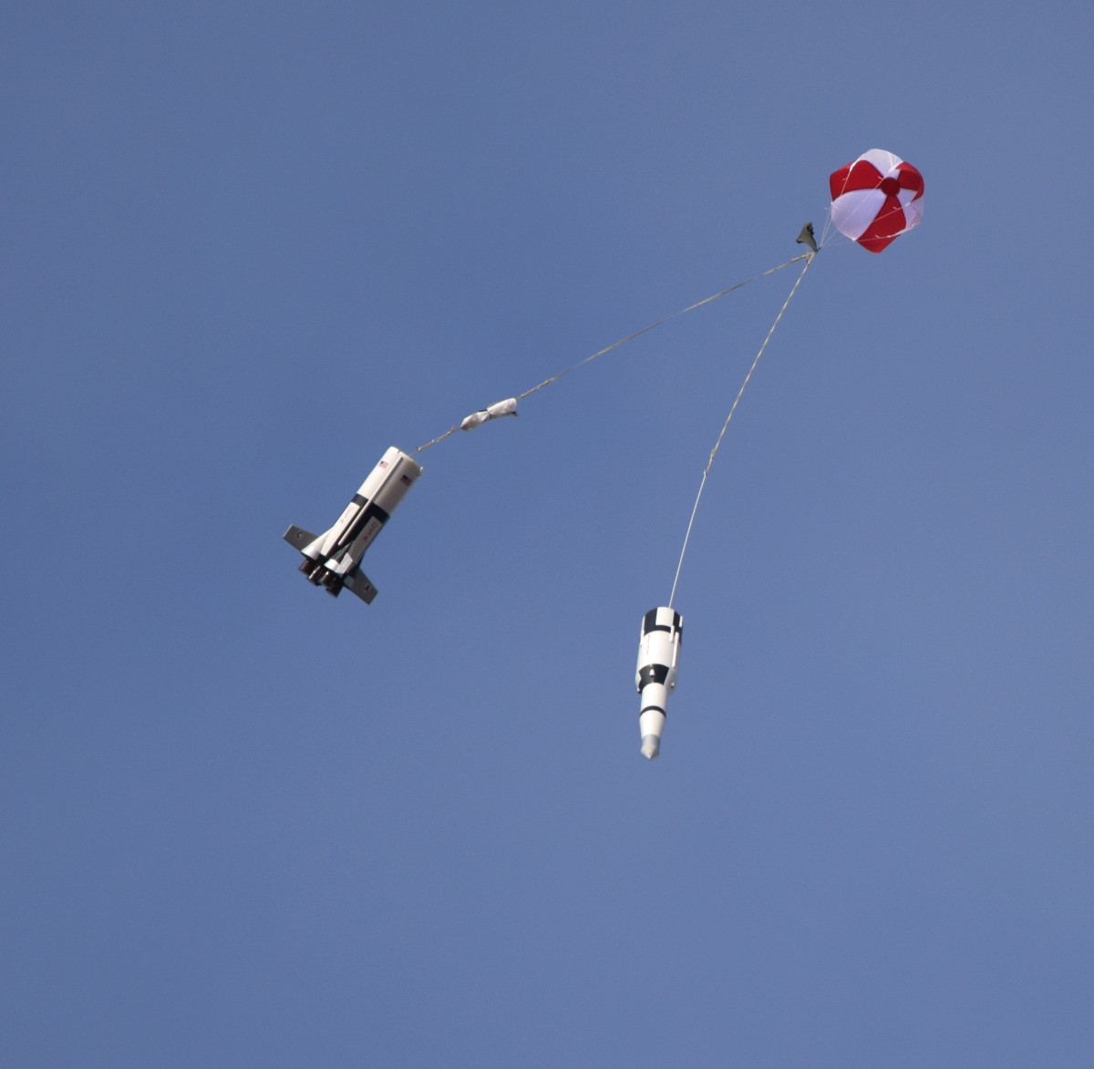
The parachutes: The rocket uses dual recovery: a
small drogue chute opens up when the motor's ejection charge fires,
and the bigger main chute is released at 210 m altitude by a
Jolly Logic Chute Release device.
Both parachutes are housed, not within the inner tube that the ejection charge
fires into, but in a separate compartment between the inner tube and the
rocket's outer skin. To make the lower compartment (for the main chute),
I used a length of commercial 75 mm body tube made
by Klima. There the parachute needs no special protection from
heat or sparks. It was only wrapped in a nylon flap to help it stay in a
tight bundle, When the top part of the rocket separates from the bottom
section, it pulls the parachutes out from their compartment. Or
compartments, as I was eventually running out of space, and had to
fashion a separate drogue chute compartment in the upper part of the
rocket at the last moment.
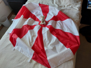
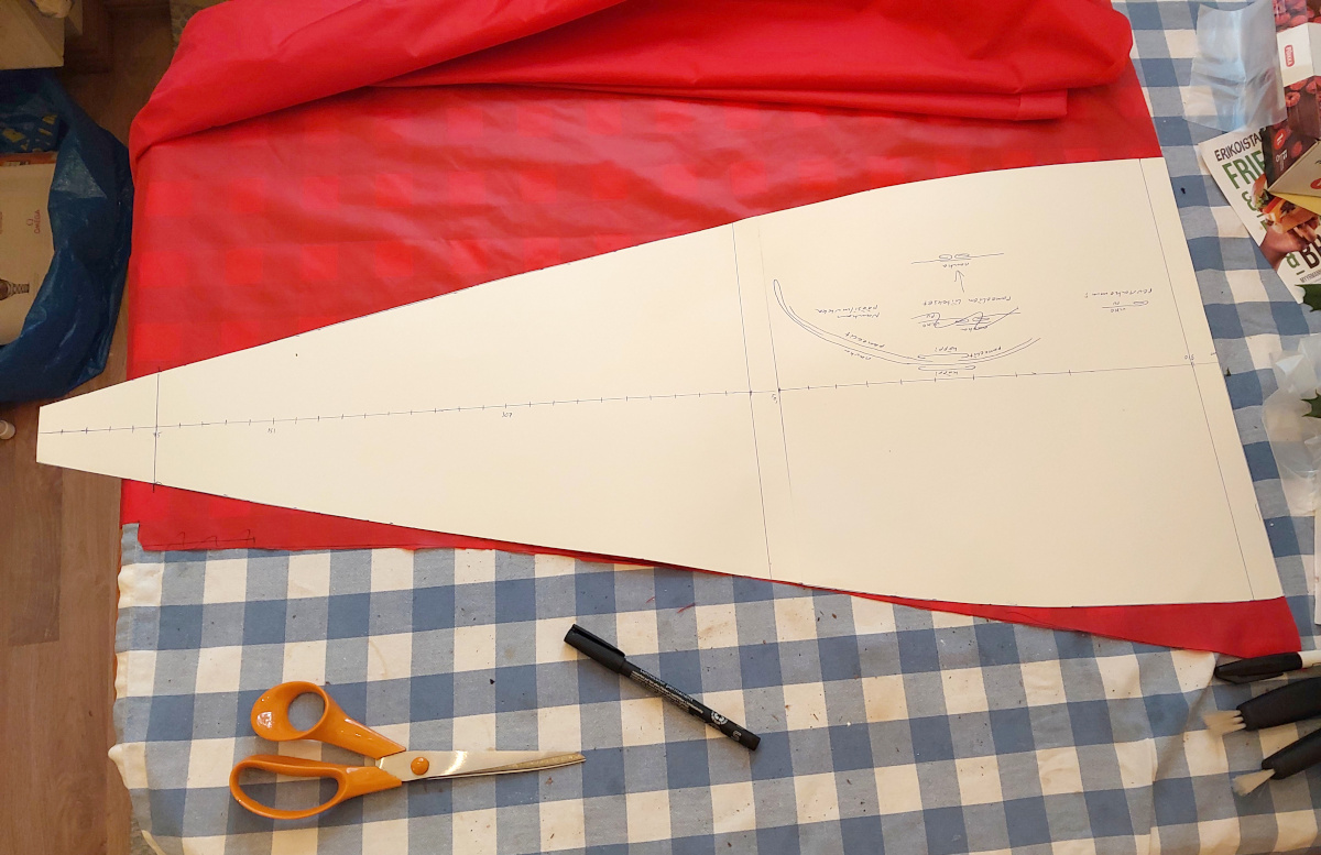
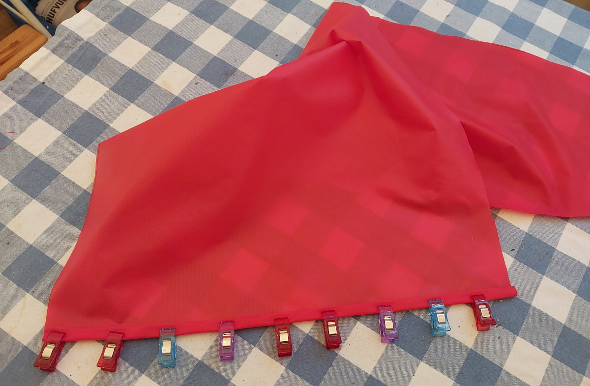
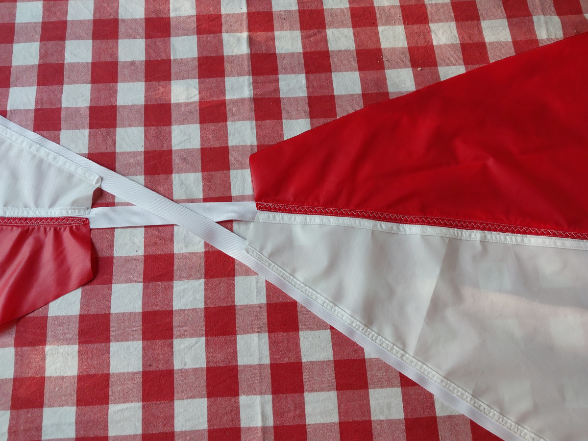
I made both parachutes myself. I wanted beautiful red-and-white parachutes,
just like on Apollo—but could not find any ready-made from the usual
online rocketry suppliers! And I had already familiarized myself with
Richard Nakka's
parachute design while working on my supersonic
Iso-Joonappi. I didn't follow his design to the letter, though. What's
the point in copying the Master's design as-is, without trying to improve on
it? In the droque chute, I used 20 mm wide polyester grosgrain ribbon
(thinner and more
flexible than the nylon webbing you see in backpack straps) for attaching
neighboring gores together, and I made loops at the ribbon ends, to which I
tied
the cords, rather than stitching them directly to the chute. That makes cord
replacement infinitely easier, if it should ever become necessary (an
impossible tangle, say), and also
much of the stress at deployment is borne by the ribbons, rather than the
canopy's fabric
itself. Do disagree with me, by all means, if this design seems stupid to
you! I'd love to hear your rationale.
Hera are a few
a few photos of the
construction of the
120 cm chute.
I wanted to make the main parachute as big as possible, and finally ended up at
160 cm diameter, but I'd tested 120 cm with the above construction
technique, and the ribbons added quite a bit of volume to the bundle, no
matter how tight I tried to pack it. So in the 160 cm version, I just
made small loops near the edge of the chute, and elsewhere I sewed the
gores directly together, hem to hem. This does not provide the added strength
I was going for above, but the chute survived just fine regardless—and
above all, it fit in its allotted bay!
|
|
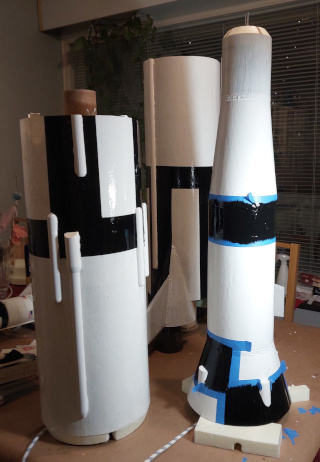
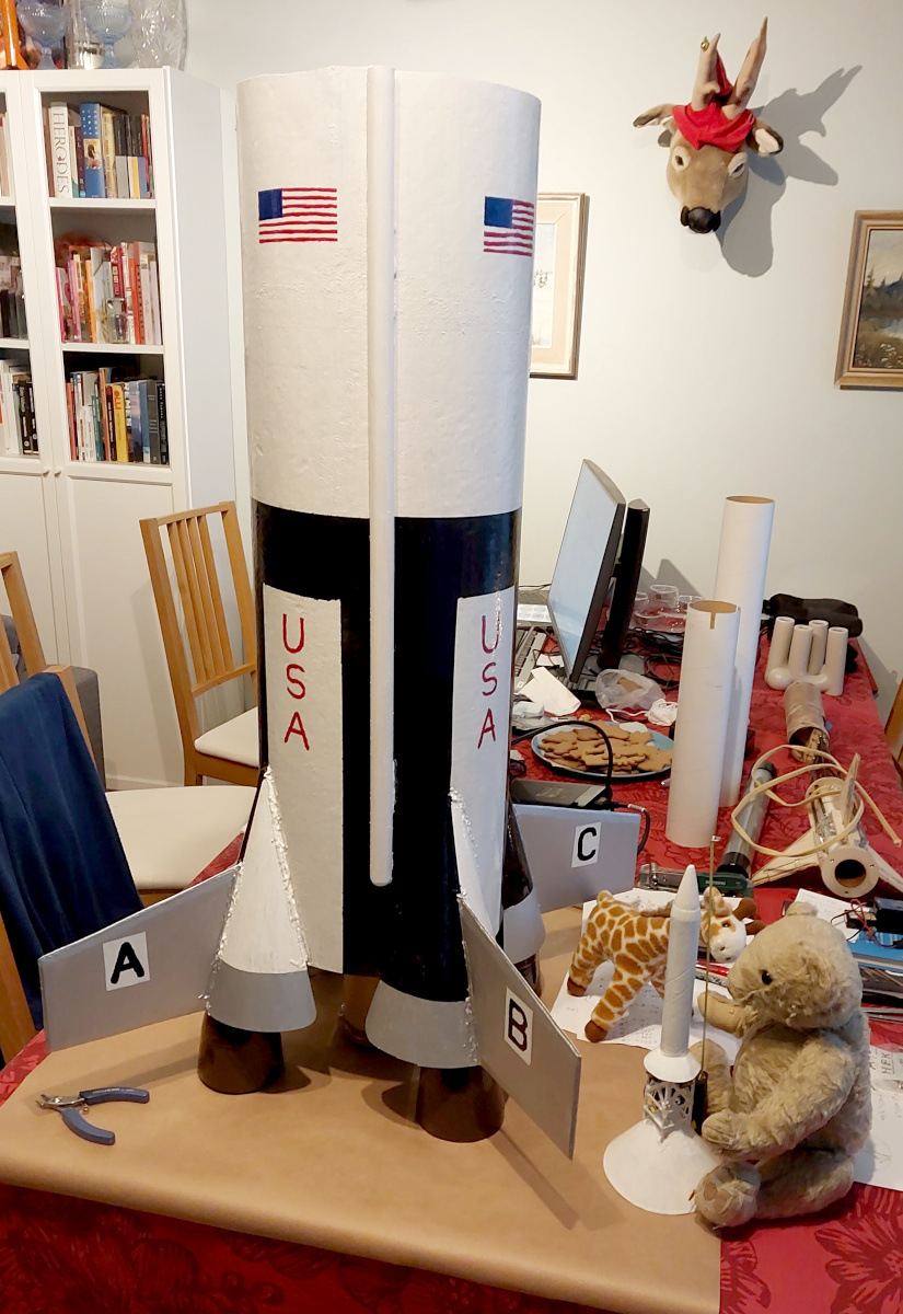
Finishing touches: I
painted the rocket mostly
with Miranol furniture paint, black and white. I freehanded the details
(flags and text) with Revell
model paints. The "dummy" engines I
painted with water-based acrylic, ugly industrial brown, and then painted
over it with epoxy. If absolutely everything
doesn't look exquisite, that's only because I knew there was a significant
probability of the rocket being entirely destroyed on its maiden flight. So
I'll go into a reasonable level of detail (note the retro rocket and cableway
fairings on the outside, which I made from semicircular-profile wood dowel,
glued on with SikaFlex 291i marine gunk), but I have to draw the line
somewhere. I.e. no, I did not freehand two hundred white
stars into the four USA flags, for example!
I received a compliment (I think) on the "Comic Sans" look of the
lettering. Too bad this photo doesn't have it yet.
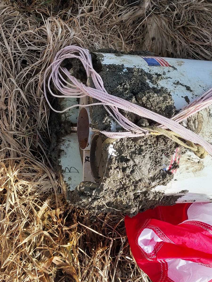
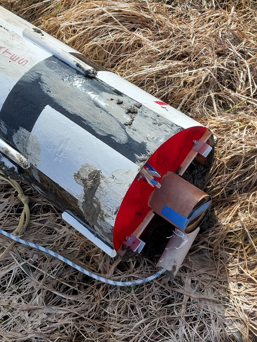
At the last minute, I began to worry about recovery deployment charge sparks
getting inside the airframe, starting little fires in the nooks and crannies of
the polyurethane foam lining. So a couple of evenings before launch, I
hastily contact cemented some
pieces of Nomex fabric to close up those
open cavities. I think that also helped keep out twenty kilos of mud, as the
rocket was being dragged by the wind catching in the main parachute
after landing.
That open part in the
above photo,
not covered by the red Nomex, is the additional parachute compartment
for the drogue chute and the upper section's recovery harness. I wrapped
the drogue into a Nomex burrito to protect it from forward-flying sparks
of the ejection charge. The main parachute
took up all the space in the lower section's parachute compartment, where
the sparks cannot reach.
|
|
Payload electronics: At the same launch event, I also flew
a roll-compensated rocket (i.e.
stabilize the spinning to get better video) which utilized a
Murata SCH16T-K10 IMU (manufactured at the place where I work). I also
logged the IMU's data, and the data from a u-blox M9 based GPS module,
for later comparison (plus air pressure, just for good measure).
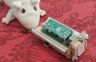
On a whim, I made a payload compartment in the Saturn
as well (another length of 75 mm Klima body tube, which the roll-comp
rocket was entirely made of, with compatible attachment rods for its
payload holder), on the opposite side from the parachute compartment, so I
could fly that logger unit a
second time. No roll compensation, of course, but
more flight track data to compare. The
logger was also equipped with an 868 MHz LoRa radio for phoning home GPS
coordinates after landing, but I didn't have time to finalize the software
for that. No matter, this rocket was easy enough to track visually. And you
can see it uses a Raspberry Pi Zero as its main brain.
The logged data was... weird. The GPS must have lost lock on takeoff, since
it thought the rocket was moving downwards! Well, the takeoff
acceleration was around 6 g, whereas the highest specified
acceleration of the
u-blox M9 chipset's airbone dynamic models is 4 g. Once the
acceleration died down and the GPS re-acquired its position, the IMU and
GPS tracks had similar features, but they were offset somewhat from each
other. With the early part of the GPS track missing, it's impossible to
say what happened to the IMU to cause this.
But I did get some apogee estimates from the logger. The GPS recorded
a maximum of 421 m, but it obviously re-acquired its position only
well after apogee. Integrating the IMU's data yields 596 m, and
the barometer's data indicates 618 m—pretty close. But these
values are significantly
less than the 949 m my OpenRocket simulation predicted. Well, what
with all the decorative fairings adding drag, and OpenRocket known to be
somewhat optimistic in its simulations anyway, I'm only slightly
surprised the apogee was that much lower in reality.
|
|
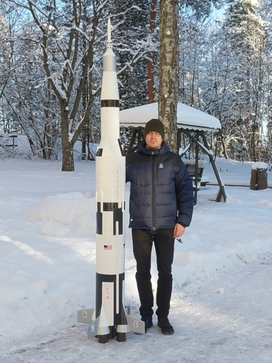
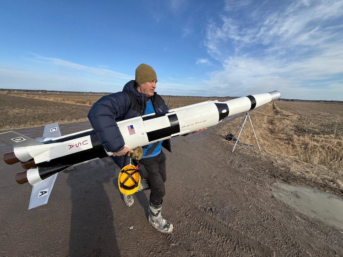
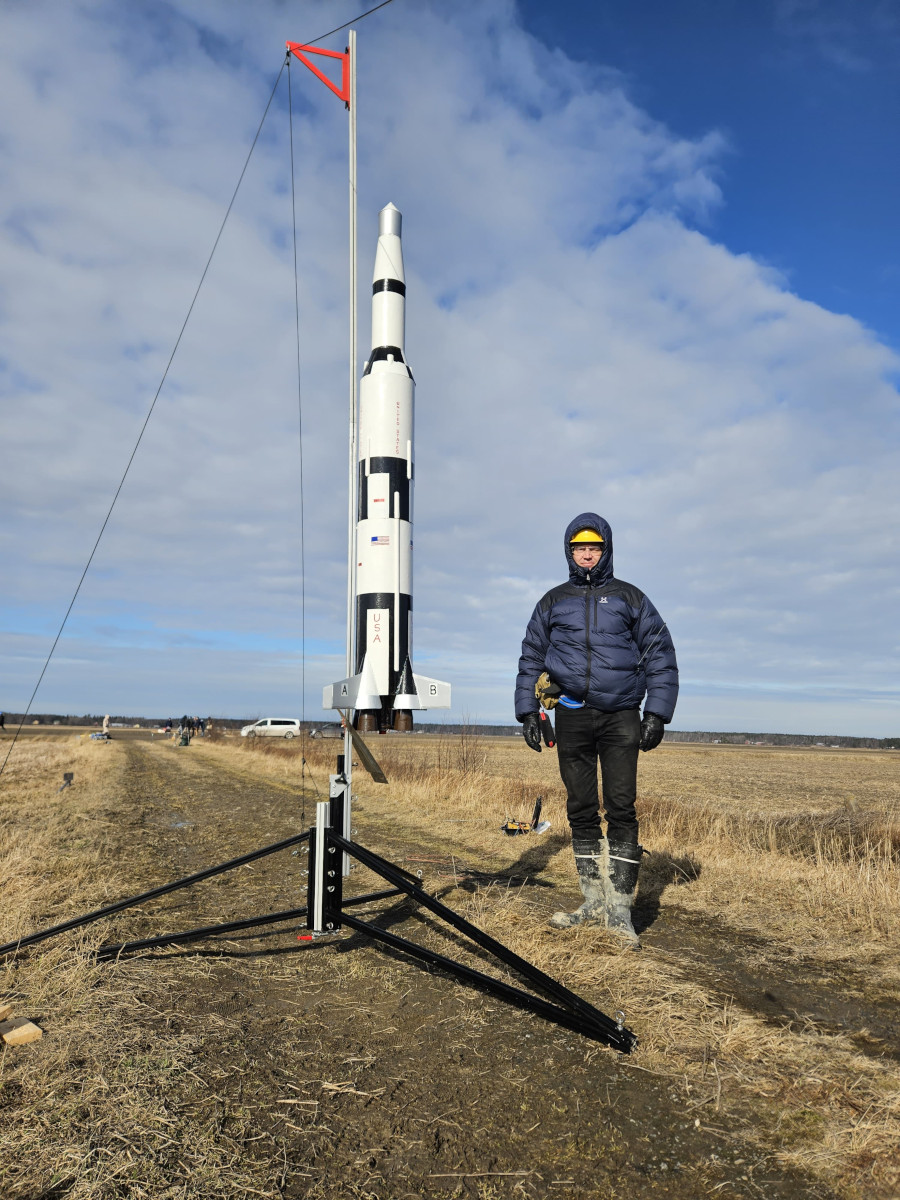
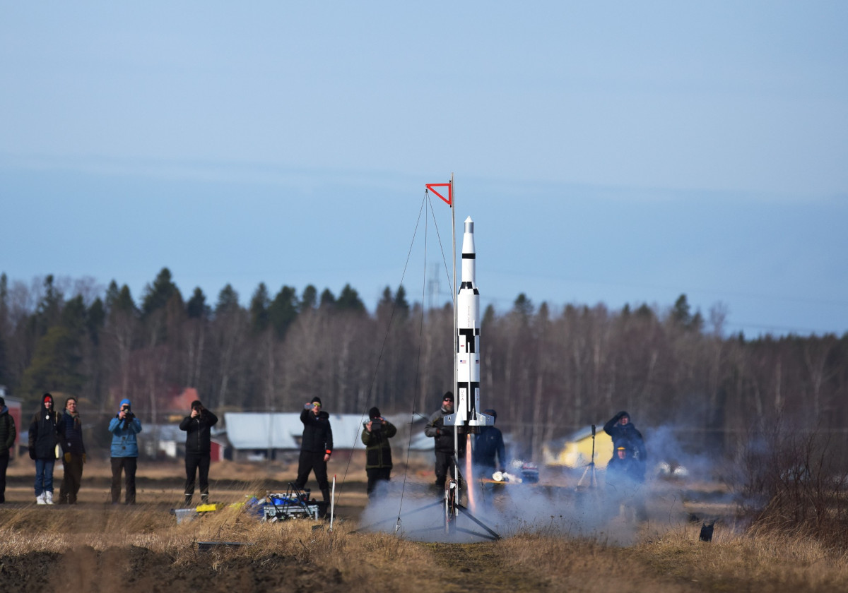
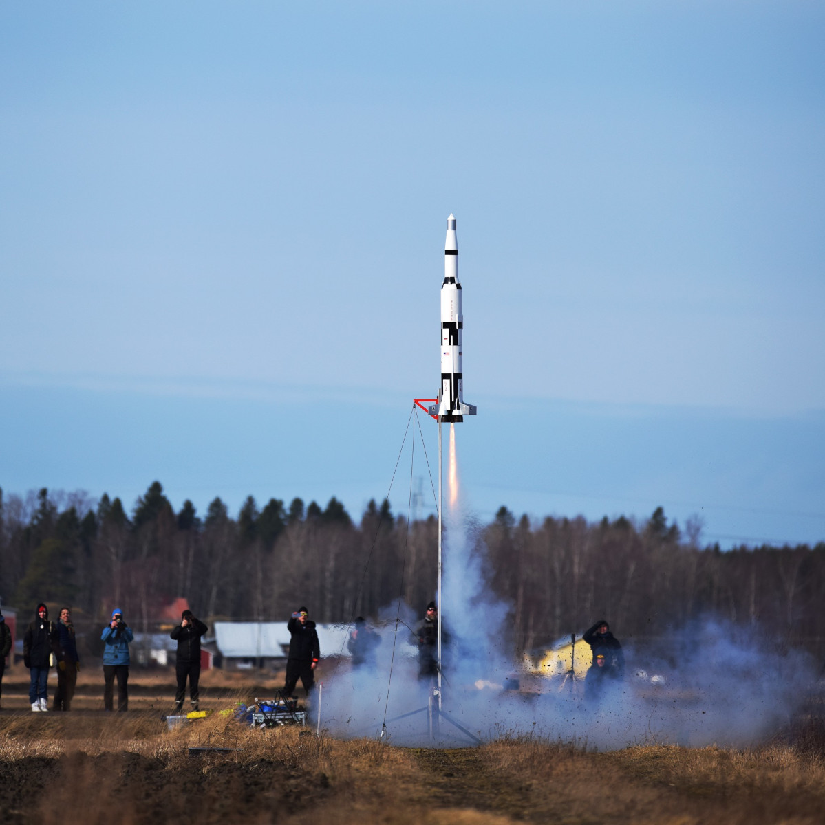
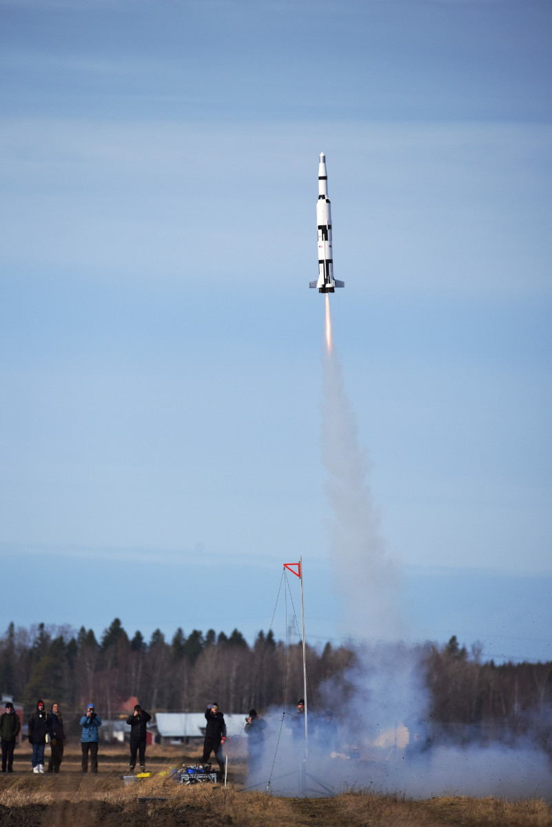
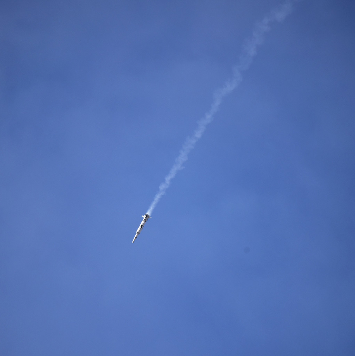
The flight: On the 28th of March, 2026, Finnish
amateur rocket history
was made, as the biggest solid-fuel rocket motor to date, a Cesaroni Pro54
2437K660-17A Classic, launched this 1:40 scale model Saturn-V I'd spent
almost a year working on. A tiny puff of smoke. Then nothing, for just over
a second. Long enough to think "It didn't light, now what?"
before
ROOAAAAAARRRRRRRRRR!!!!!!—the 9.7 kg monster lifted,
light as a feather,
to some 600 meters altitude, separated cleanly, deployed its drogue chute,
came down fast as designed, and even the Jolly Logic worked as it
should—WHAPPP!!!—the main opened up, and the rocket
touched down softly. Textbook.
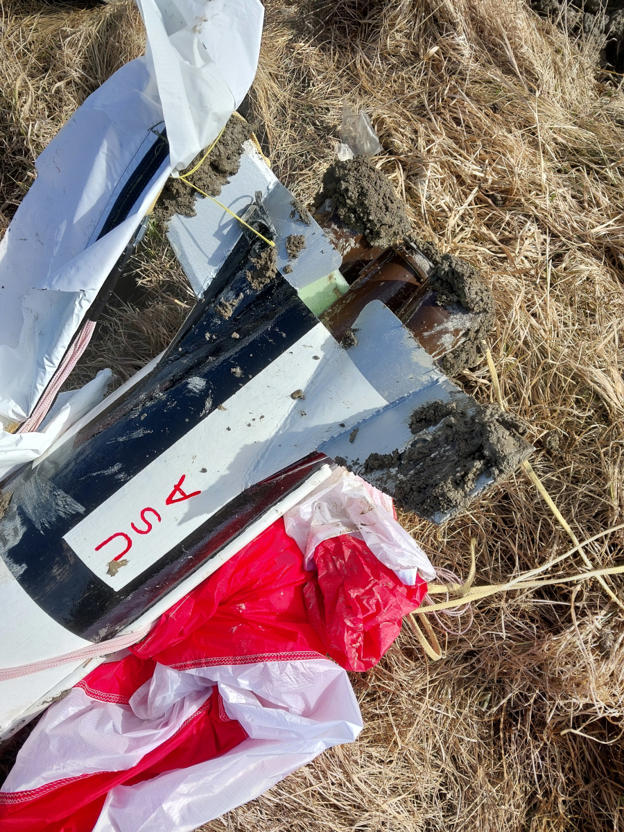
Then the wind caught onto the main parachute, and started dragging the
rocket through the mud. Yuck.
Before. (Photo by Mika
Järvenpää, with permission)
Before. (Photo by Mika
Jalava, with permission)
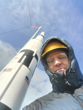
Before. (Mandatory pre-launch
selfie)
After. Yuck.
After. Blechh.
After. What a mess.
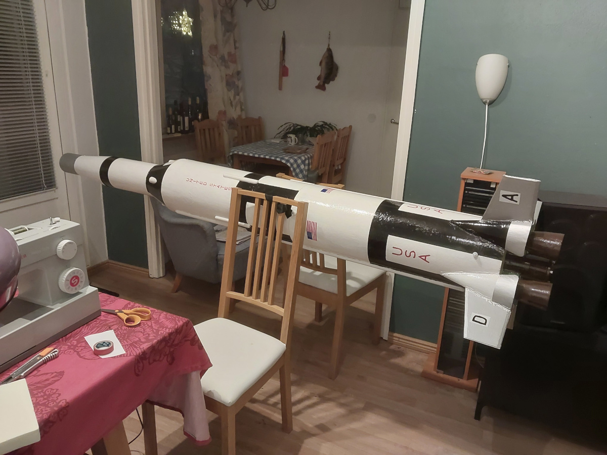
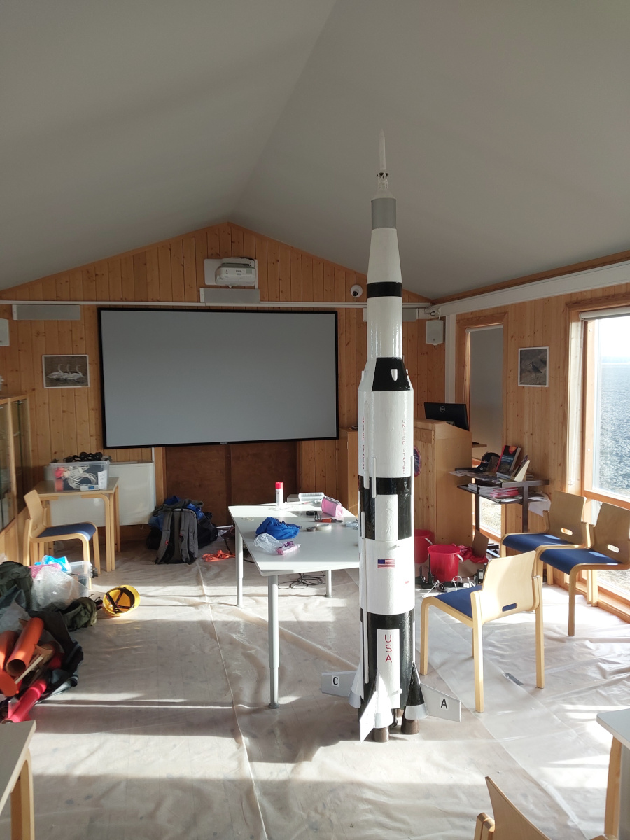
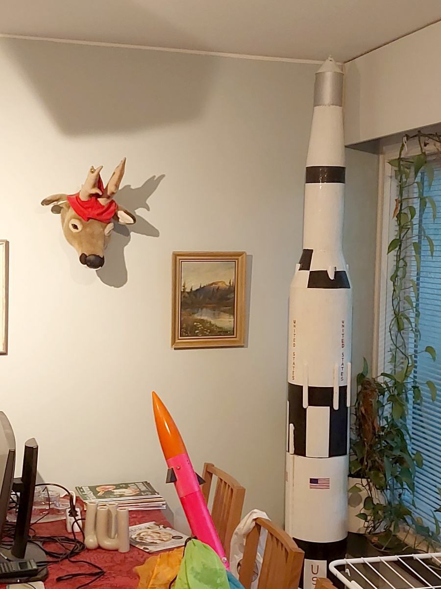
But it survived intact. I got my Level-2
certification. After a lot of cleaning
(the combination smell of ammonium perchlorate and agricultural poo is
absolutely evil!), the rocket is now standing
in our living room.
Gotta find a better place for long-term storage.
The launch itself made it all worthwile.
Here
are
five
amazing
photos
by Jan Holmgård, with permission.
|
I don't mean to put a damper on your ambition, but unless you've mastered
the basics first, you'll have a really bad time doing anything
like this. Learn to walk before embarking on a Marathon. You know?


