|
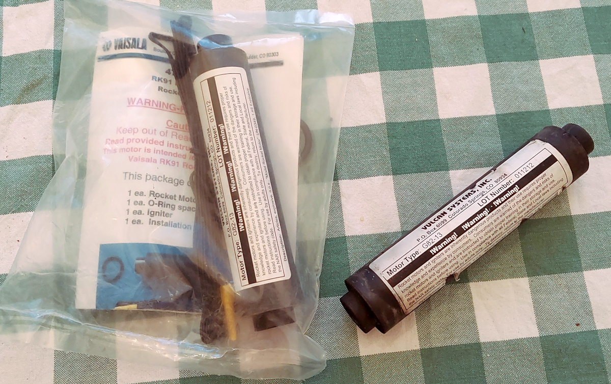
Way back in the 1990s, when rocketry was a lot more limited and
strictly regulated in
Finland, we only had A, B, C and D motors available, one type of each,
from one manufacturer. Nowadays things are different, and there are a
couple of Finns already into high power rocketry (even I myself have an
L1 certification now). But way back then, through
a totally improbable happenstance, a limited number of
Vulcan Systems
G82-13 motors became available to us, as leftovers from
Vaisala's old
rocketsonde business. These mid-power motors were huge by our
standards back then! I bought a couple of those motors, plus one of
Vaisala's rockets as well.
My brother Sampo, who initiated the
OpenRocket software through his
M.Sc. thesis work (which subsequently took off like a roc... um...
like pike from the shoreline),
was convinced that such a G motor might just
push an optimized rocket past Mach 1. So, in conjunction with a
couple of
Haisunäätä
launches,
he launched tiny, optimized rockets on
these monster G motors, trying to verify breaking the sound barrier.
Onboard each was a barometric altitude data logger. But he never found
the rockets after flight for data offloading and analysis...
Fast forward to the spring of 2024, and the
Finnish Astronautical Society
is launching
student built CanSats to about 1 km altitude using I motors,
something totally unthinkable in days gone by... On the way back home
from the launch site in the
Söderfjärden Meteor Crater
near Vaasa, I got
to thinking about Sampo's old project, and the couple of G motors I still
had stashed away. (They're not really practical to use without dedicated
air space, so I never got around to doing anything with them.)
I decided to try my own hand at Sampo's idea, but using an approach that
doesn't strictly require the rocket to be found afterwards—Doppler
measurement. Thus was born Iso-Joonappi, a fiberglass airframe
flying on an ancient G motor, carrying a radio transmitter. The rocket
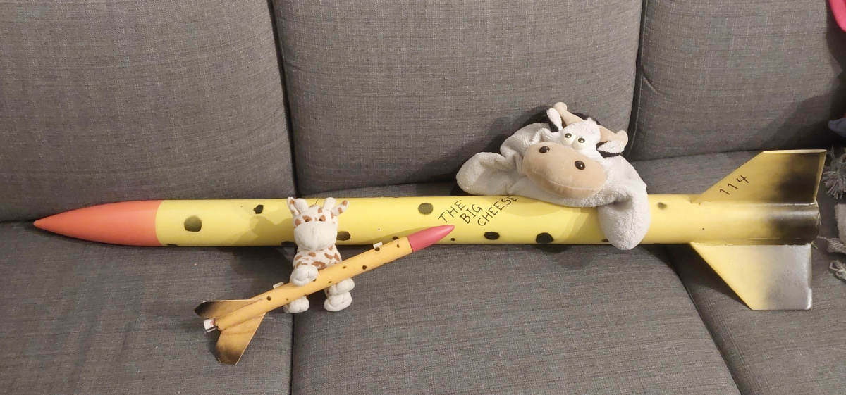
flew the following year, at the 2025
CanSat launch (where I also flew my L1 certification flight with one of
the CanSat lifters I built,
The Big Cheese).
|
|
|
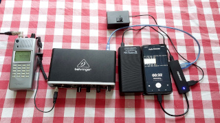
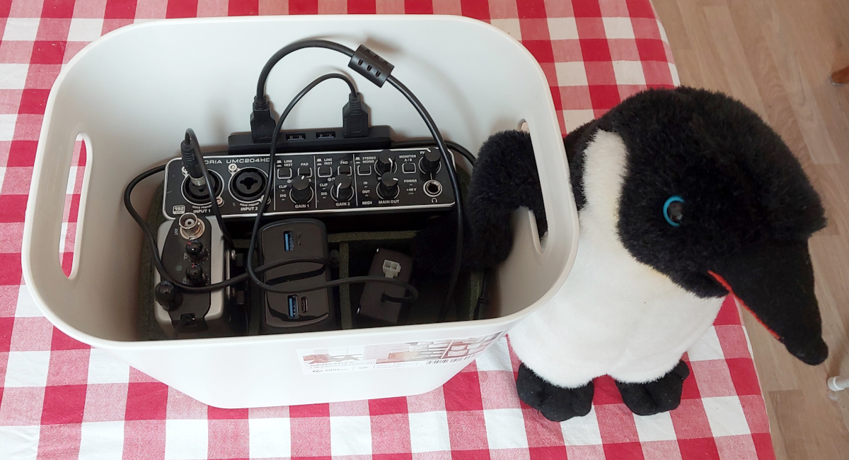
The radio receiver is a Yupiteru MVT-9000 Mark-II (M3) scanning
receiver. It's a typical "DC to daylight" scanner, but one of
the very few that have SSB reception.
The radio's output is wired to a Behringer UMC402HD audio interface,
connected via an Axagon HUE-C1C powered hub (powered from a
Cloudberry H330PD USB power bank)
to an old Android phone, which records the audio using some app.
(I guess the radio could be wired directly to the phone's audio jack with
a suitable cable, but a proper audio interface has the advantage of
manually adjusting the audio gain, rather than allowing the phone's
automatic gain to mess things up.) The headphone output of the UMC402HD
fed into a small speaker (not shown) so I could fine tune the radio's
frequency before launch.
The box at the top in the photo (also powered from the power bank
via the hub) is for switching the rocket's radio transmitter between
standby (intermittent short beeps) and flight mode (constant transmission).
A 40 m long cable extended from that box to the launch
pad, where it controlled a 5 V reed relay. The relay's switch
contacts were wired to the rocket's onboard control system via a 3-pin
header, which yanks out when the rocket takes off. One of the pins breaks
contact at that moment, informing the control system of takeoff. (A specified
time after takeoff, the radio is switched back to standby.)
|
|
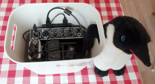
I assembled the above instrumentation into a cheap plastic box which I lined
with a glued-together frame of closed-cell foam. This keeps everything where
it should be, and I don't need to worry about interconnects going awry when
setting up a bunch of separate devices. Just connect the receiving antenna
(see this photo, front
left—the helical beam antenna was originally built for receiving
telemetry from the Iso-Haisu
hybrid rocket)
and the rocket's remote control cable, power up and launch.
The penguin's name is A. Forstén. He just photobombed for his
own amusement. Penguins will do that.
|

|
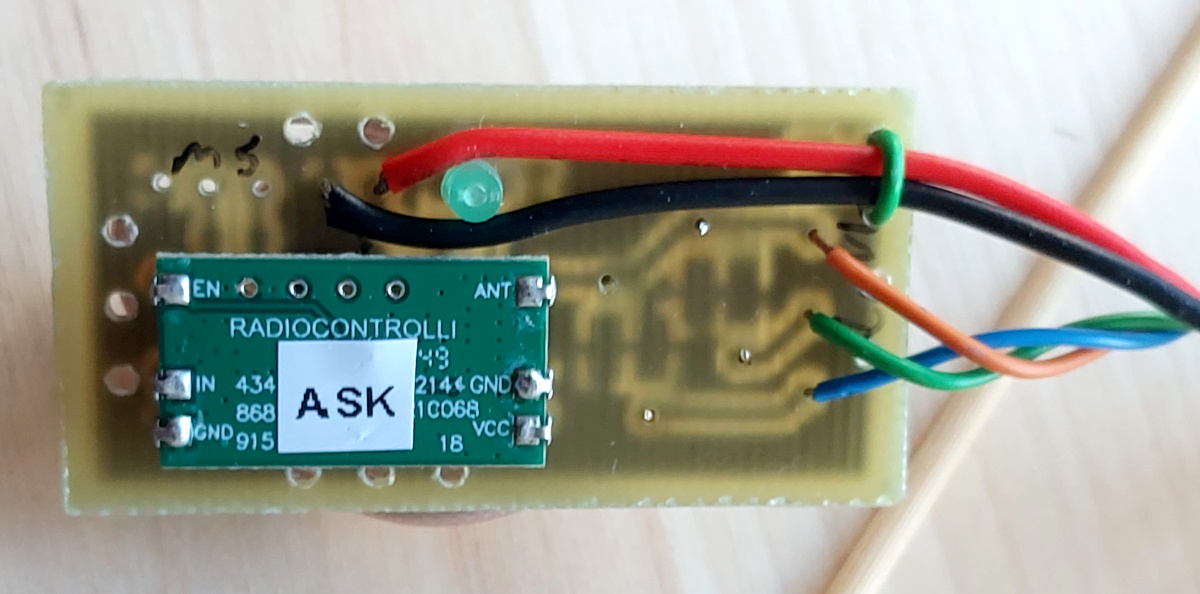
The transmitter
I ordered an 868 MHz transmitter module from
Radiocontrolli Italy, and etched
a small PCB for a PIC12F508 microcontroller and RF phasing lines for
feeding the tripole antenna. The
device transmits occasional beeps, and prior to launch it is
switched to constant transmission mode (as it takes ten seconds or so to
stabilize). After launch it still
transmits constantly for a dozen seconds or so, before resuming occasional
beeps to comply with the duty cycle limitations on the frequency. Remote
control of the transmission mode, and detection of launch, is accomplished
through a three pin header at the bottom end of the rocket, which gets yanked
out on launch. After landing, the ongoing
beeps from the radio enabled finding the rocket.
I made a compartment for the radio and its tiny LiPo battery out of
fiberglass. The compartment takes up half of the rocket's body tube's
cross-section
in the forward part of the tube, and is closed at its lower end. This
allows the ejection charge to pass the radio without damaging it. Also the
shock cord is protected by the same compartment. (No recovery wadding was
used anywhere.)
|

|
The antenna
You read the above right, I did say tripole antenna. I wanted a
circularly polarized signal, since (1) a linearly polarized signal
and receiving antenna would cause occasional nulls as the rocket rotates,
and (2) a linearly
polarized signal with a circularly polarized receiving antenna would lose
about 3 dB of signal. I already had the RX antenna left over from the
Iso-Haisu project. In it,
the onboard TX antenna was a QHA (Quadrifilar
Helical Antenna), which produces a beautiful hemispherical radiation
pattern with perfectly circular polarization, but the necessarily
narrow body tube of
Iso-Joonappi couldn't take such a large antenna. Besides, I wanted to
receive the signal from directly underneath (of course, for the Doppler
measurement), where any antenna inside the body tube might be hidden behind
the rocket motor's flame, its ionization attenuating the signal too much.
So I wanted to place the radiating elements in the fins of the rocket. A
dipole antenna at 868 MHz will just fit in the fins in "sloper"
configuration. But a dipole will be linearly polarized (plus it radiates
broadside all over the place). To get circular polarization, I considered
a pair of crossed dipoles, fed 90° out of phase. That's the traditional
method of producing a circularly polarized signal (and it's also more
directional, radiating mostly upwards and downwards). But that would need
four fins, and that caused too much
air resistance, according to my simulations. Luckily there had been lots
of discussion on tripole antennas on the Finnish ham radio email lists.
I basically fed three monopole antennas, one directly, one through a
1/3 λ phasing coax, and one through a 2/3 λ
coax. The coax braids were connected together at all ends, and tied to the
radio module's ground pin. Simple enough, though I have no idea what the
impedance of the feed point is! I just hoped the TX module wouldn't mind
the SWR too much. And it didn't; that's one benefit of a QRPP TX.
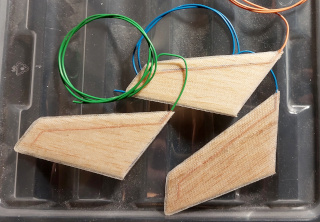
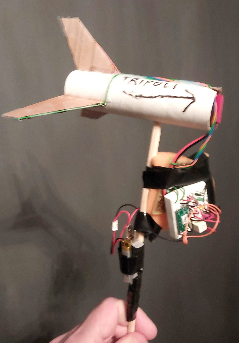
The photo shows a
cardboard mock-up of the rocket's rear end, with the tripole elements
fitted to the fins. Attached is the PCB with its coax phasing lines, with
the TX module and its controlling PIC microcontroller still on breadboard.
I used this awful prototype to verify that the antenna does produce
a (sort-of) circular polarization, and that it does have (at least
some) directivity. Ok, it's nothing spectacular on either front, since I
just don't have the space or weight budget to do things properly... But it
seems to work (and even the polarization direction is correct), so this
design is going on the rocket!
|

|
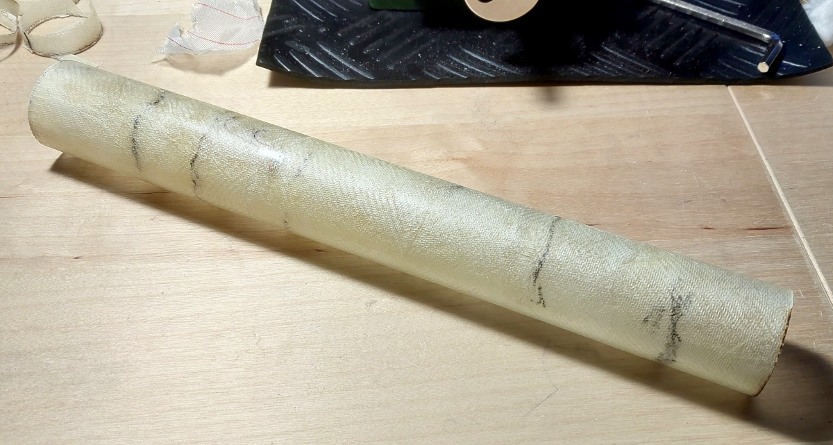
The body tube
The glass fiber
body tube was tedious to make, as I wanted a maximally smooth outer
surface. I made a tube form out of several layers of paper glued together,
lined its inside with baking parchment (epoxy does not stick to that),
and applied epoxy-soaked glass fiber fabric
(about 150 g/m2 I think, two layers everywhere)
inside it, piece by piece, allowing it to cure between additions. I squished
the laminate between the baking parchment on the outside, and the release
and absorbent fabrics on the inside, by stuffing wads of absorbent
fabric inside the tube to apply pressure.
It took ages to build up the approximately
300 mm long tube, but it turned out rather good!
I did also try to simply roll up a sheet of epoxy-soaked fiberglass fabric, and
press it against the tube form from the inside using an inflated
bicycle inner tube. That did not turn out well at all.
|

|
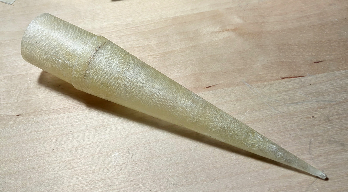
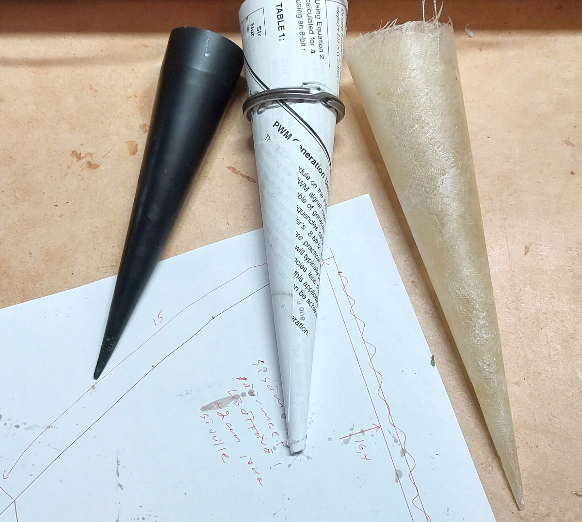
The nose cone
I made the nose cone in a similar fashion, adding fiberglass bit by bit. This
also took ages. Again, I wanted a smooth outer surface, so I made a
paper form, which I lined with baking parchment, and began building the nose
cone inside that. I used the old Vaisala rocket's nose cone as my initial
mold to make the paper form (which I reinforced with a suitably sized metal
keyring to ensure its cross-section stays circular). You can see the Vaisala
nose cone, the paper form, and the completed fiberglass cone in
this photo.
Then I fabricated a short segment of fiberglass tube to fit inside the body
tube, and epoxied that to the cleaned-up nose cone. You can see the final
result here.
|

|
The motor mount
This was a bit less of a hassle to make. I wrapped the actual motor in a
suitable thickness of paper, then wrapped baking parchment over that, and
finally the epoxy-soaked fiberglass fabric over that, followed by release and
absorbent fabrics, and squeezed it all tight with a couple of meters of
elastic band which I wrapped around it. After curing, I cleaned it up, cut
it to length, attached a motor retainer clip (made of piano wire) with a
strip of fiberglass fabric, and attached the forward end stoppers (made of
flat fiberglass composite) with epoxy. The forward end stoppers also protrude
outside the motor mount, centering it inside the body tube. When assembling
the rocket later, I glued those to the body tube's inside wall.
|
|
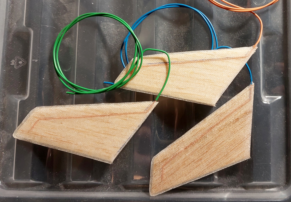
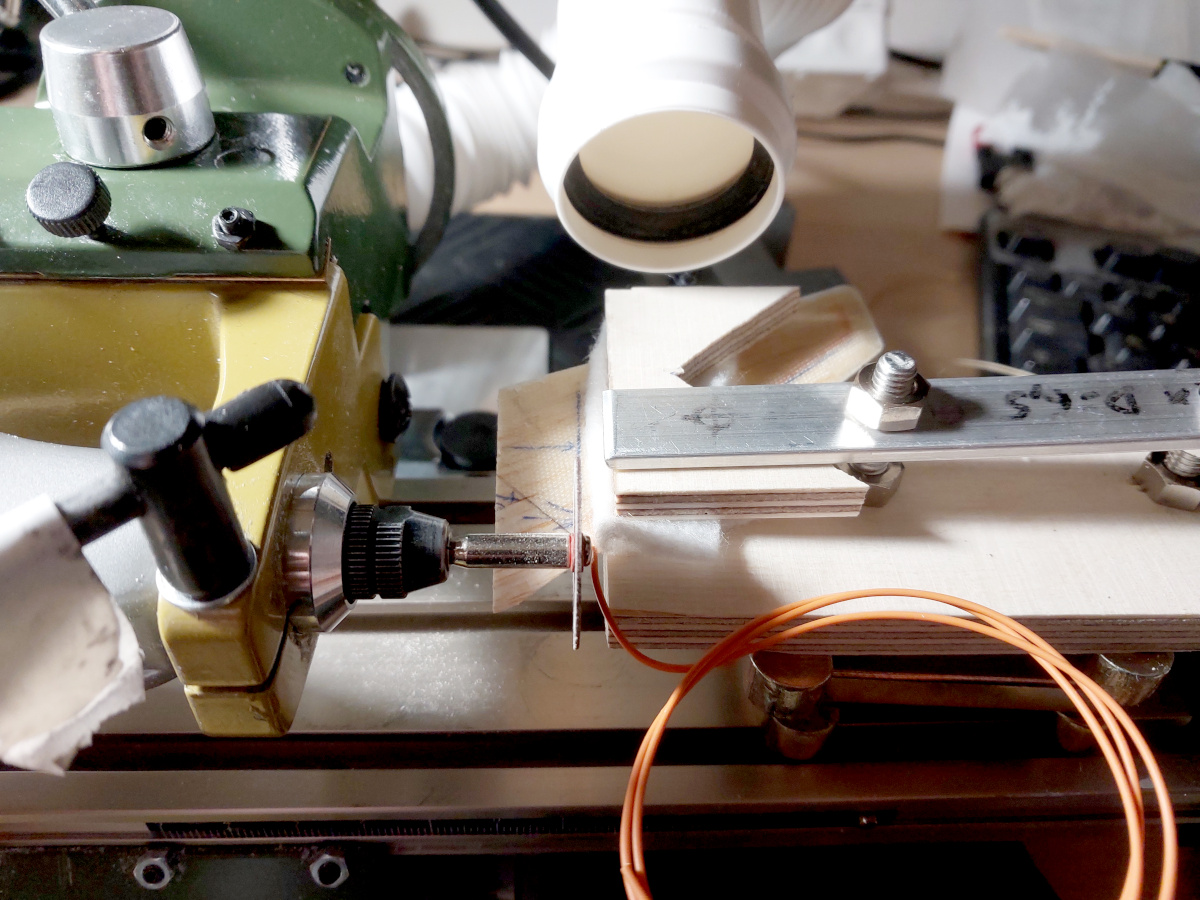
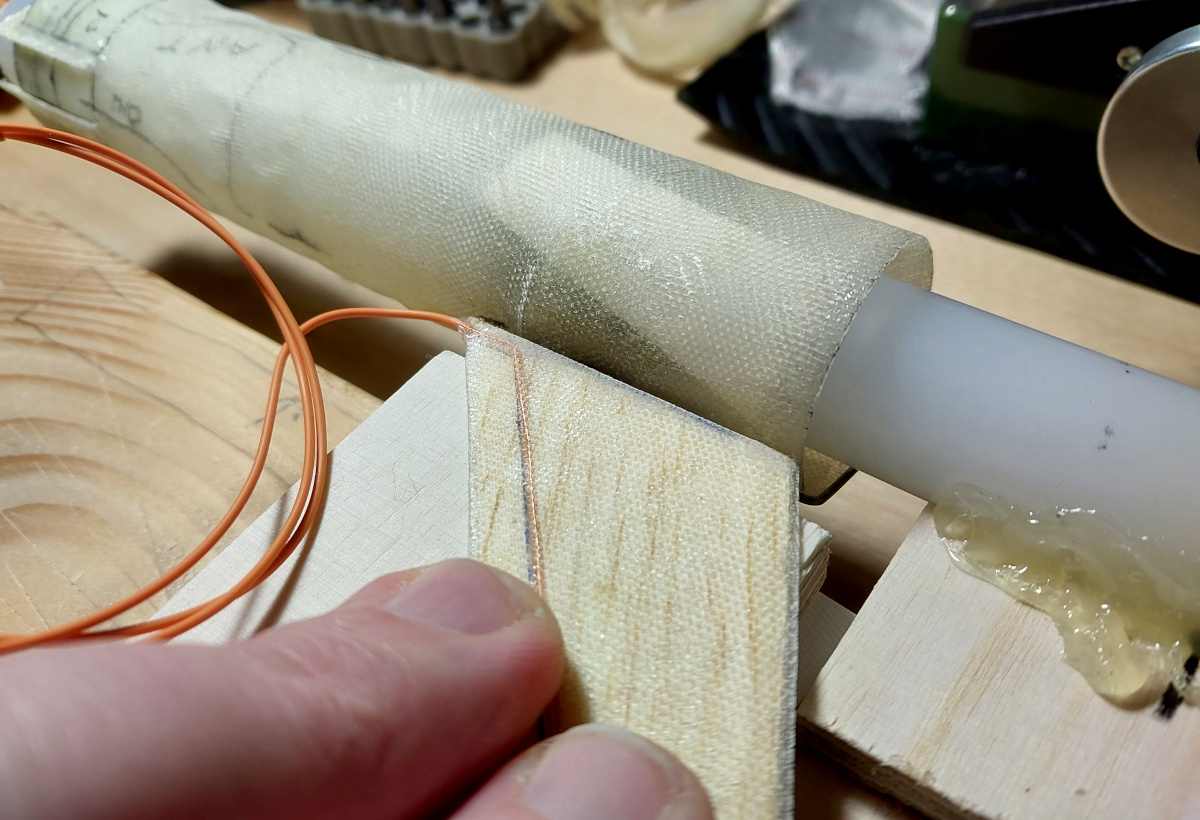
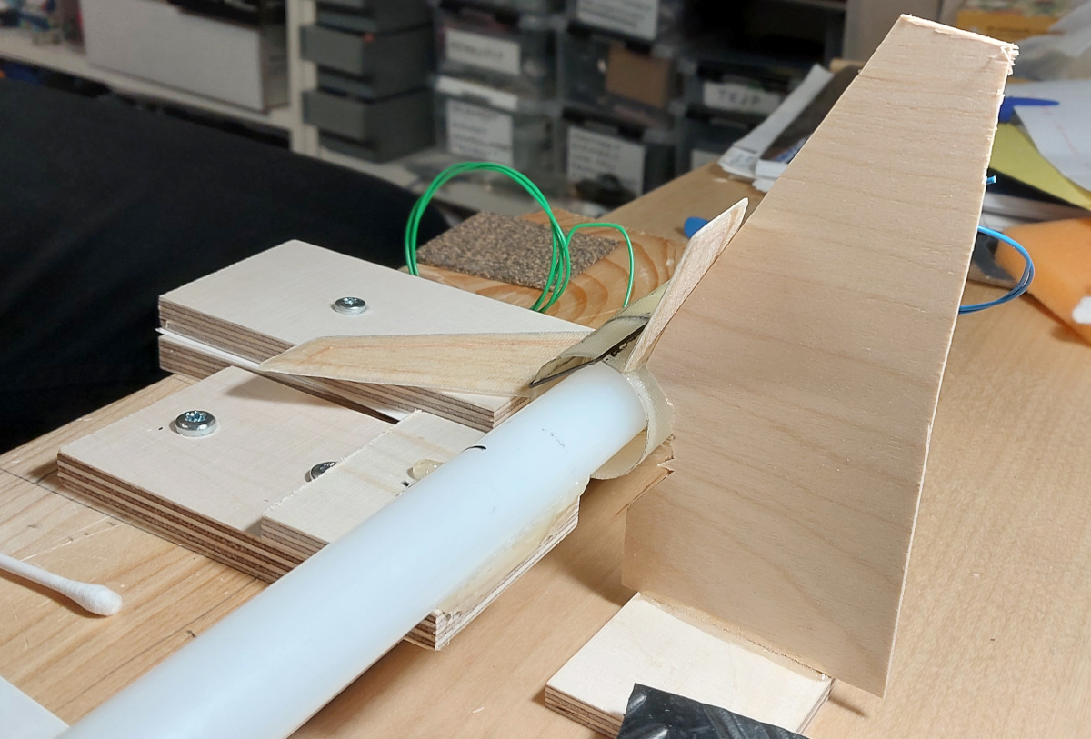
The fins
The fins are made of 1 mm thick balsa sheet, laminated twice with
extremely light fiberglass fabric (50 g/m2, I think).
Before laminating them, I milled grooves for the tripole antenna wires,
and epoxied the wires in place, filling the grooves at the same time. I
also beveled the edges of the fins with sandpaper. The first layer of
fiberglass was open at the forward edge, though I left about a millimeter
protruding forward from the balsa's edge, and the layers are nicely
stuck together with no gap visible. The second layer was similarly open
(but protruding a millimeter, and stuck together) at the tailing edge.
The tip chord also has a millimeter of fiberglass protruding, and is nicely
closed as well. I intentionally left a bit of extra balsa at the root chord,
which also got laminated, and which I trimmed away last
(using my Proxxon setup; there's a photo
here, but I don't
know if you can make out what's happening in that mess...), to leave its
edge as square as possible.
|
|
I contrived a jig to hold the motor mount from its inside, and to glue the
fins to the motor mount as evenly spaced and perpendicular as possible
(see a photo of the
jig, which comprises a rod with thick layers of tape wrapped around it
to hold the motor mount from the inside, attached to carefully positioned
scraps of plywood to place the fin at the correct height). With the first
fin in the proper place, I first made a fillet on one side of the joint,
and after a paranoid long curing time, rotated the mount and made a fillet
on the other side.
Then I repeated the process for the other two fins. I made another separate
jig with a 60° angle on it to place the following fins at their
correct angles respective to the first (as shown in
this
photo—a scrap of plywood with a 60° slope, glued perpendicular
to another plywood scrap). My fins have never been this
straight and even!
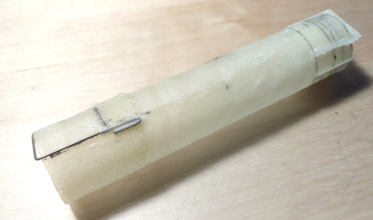
Finally, I cemented the tripole antenna's wires, as well as a 3-wire control
lead for the radio transmitter, to the outside of the motor mount. I placed
short lengths of heat resistant fiberglass sleeve over the wires forward of
the motor mount, to protect them from the ejection charge (as seen in
this photo).
|

|
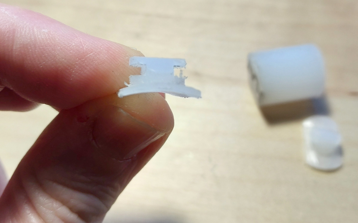
The launch lugs
I wanted the launch lugs to be as low profile as possible to cut down on drag,
and I had barely any room inside the rocket, especially between the motor mount
and the body tube. So I machined custom launch lugs out of Nylon rod with
my toy Proxxon mini drill. The two lugs stick out
of the body tube through 10 mm holes, and are held in place from the
inside, the lower one by the motor mount, the upper one by a piece of
fiberglass cloth epoxied in place. The lugs fit into a 20×20 mm
rail.
|

|
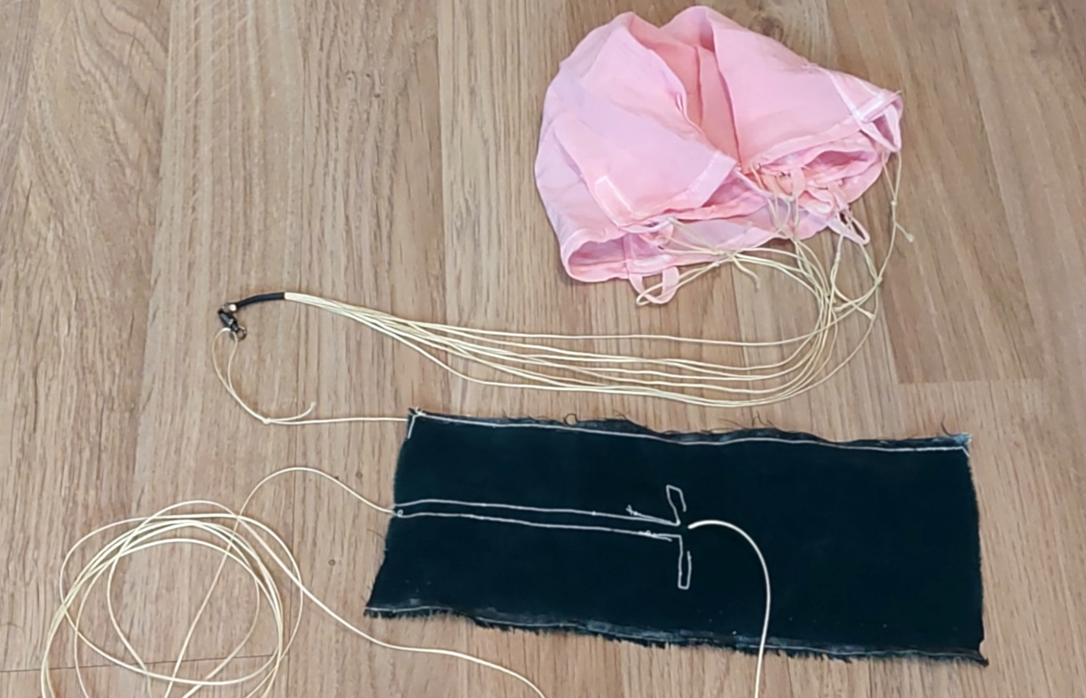
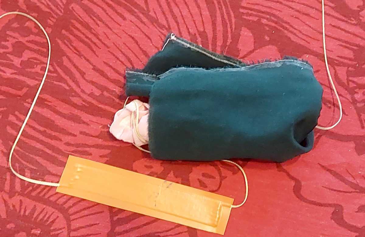
The recovery system
I made a small
parachute out of silk, which I managed to dye an awful
underwear pink. The parachute lines and shock cord are all 0.75 mm
Kevlar. There's an additional flap of silk that wraps around the packed
parachute.
I've seen steel thread of crazy strength snap when the
ejection charge shoots out the nose cone. Therefore I made
a lengthy
zigzag of Kevlar cord onto a piece of sticky tape, which I then
folded in half. This will "give" about a meter, reducing even
the most violent yank to safe levels. (In the end, this wasn't even
necessary—none of the cord was pulled out from the tape sandwich.)
The packed parachute was
wrapped into a burrito
inside the extra flap I mentioned above. The burrito and the sticky tape
thing fit inside the hollow nose cone.
|
|
|
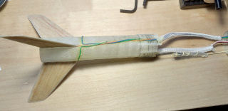
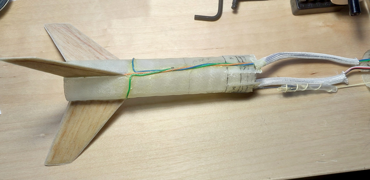
The completed rocket
Slots were cut at the bottom end of the body tube, and the fin can was
inserted. Fillets were made on both sides of each fin, and for good measure,
an additional strip of the extremely light fiberglass (which the fins were
laminated with) was laminated over each fillet.
Finally, the rocket and its nose cone were sanded, gooped up sparingly with
epoxy, sanded again, and painted RAL 2004 orange.
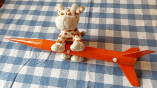
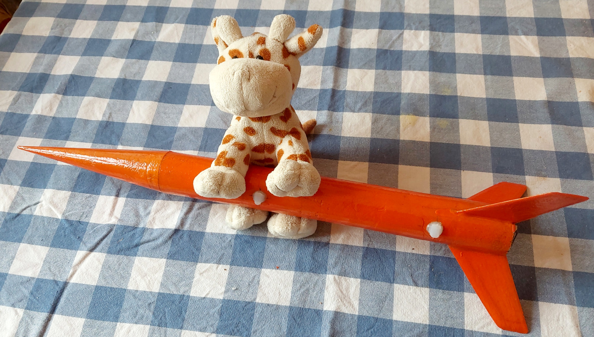
Roope (the furry cow) can't wait for the launch event. He's going to ride
onboard my HPR L1 certification rocket
The Big Cheese!
(Not the supersonic
Iso-Joonappi,
though.)
|
|
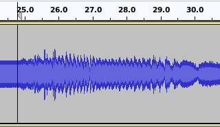
The data
If you want to listen to the raw data itself, here you go:
data.wav.
Yes, that's the audio straight out of the radio receiver, received in
upper side band mode. That's the RF Doppler effect right there, downconverted
into audio. Cool, huh?
Unfortunately, due to a total brain fart, I had programmed the rocket's
radio transmitter to shut off just a few seconds before it reached apogee!
Damn. If it had transmitted continuously just a few seconds
longer, I could have integrated the altitude of the rocket
from the measured velocity. Now I'll never know how high it went.
Stupid!
But peak velocity is what I was primarily interested in. (Or,
only interested in, apparently, at the time I programmed the radio's
controller...) So, exactly
what velocity does the maximum frequency shift correspond to?
Above or below Mach 1?
|
|
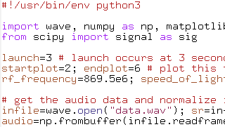
The analysis
After cropping the relevant part of the audio file, I began working on it
in Python. Now, I'm a complete, hopeless newbie in Python, so forgive me
if I seem to be coding with my left foot. Also, I'm certain the
SciPy libraries
contain proper Fourier transform functions ready made, but as I
was not familiar with those in advance, and since my signal was clean
enough (i.e. not buried in noise), I simply low-pass filtered the
audio, located the zero-crossings, counted the intervening samples to obtain
the sine wave's period, and got the instantaneous frequency from there.
There was plenty of quantization noise, and the occasional extra blip,
but a second low-pass filter took care of those.
Here is the code that will read the above audio file and display a plot
of Mach number versus time after launch:
analyze.py.
|
|
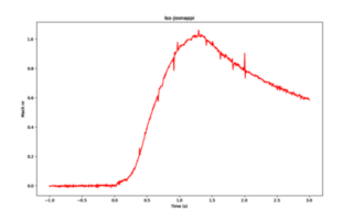
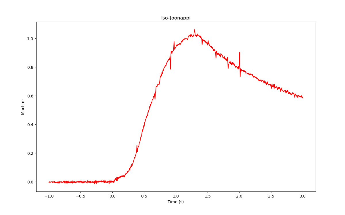
The results
This graph,
produced by the above Python script, shows
the rocket's velocity right after launch. Let me emphasize, this is not
height—the maximum just after the 1 second mark is not the
apogee, it is the maximum velocity! After the graph's
maximum, the rocket was still going up like a disoriented pike, but its
velocity was slowly decreasing. Apogee wasn't reached for another
ten seconds!
And as you can see, the rocket just reached Mach 1.0!!!
(Calculated using the speed of sound at 0°C, which was the day's
approximate temperature, if not somewhat cooler still, so technically my
rocket may have gone even a couple percent more above the local speed of
sound.)
I wish I could draw a graph of the rocket's height up to apogee, but as I
mentioned above, just a bit of the necessary data is missing. *Facepalm*.
According to the simulation, apogee was at 1.3 km.
But Mach 1.0!!! On a G-motor!!! Woot!!!
|
I doubt I'll try again with the same rocket or the same motor, but I'll
certainly repeat the Doppler measurement thing with other rockets and other
motors! It worked just swimmingly! And now that I have my L1 certification,
I can surely go past Mach 1 on an H or I motor!
