|
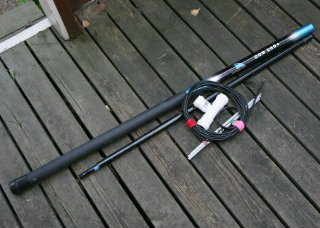
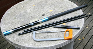
I had an 8-meter long fiberglass fishing rod waiting to be put to use.
I discarded the top two sections, used the next two for the boom, and the
rest for a mast. The telescoping mast is thus 4 m tall and easily
handled. The two-section telescoping boom is long enough to accommodate
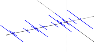
five elements on 2 m and eight on 70 cm on the dualbander, or
six elements on the 2 m monobander.
|
|
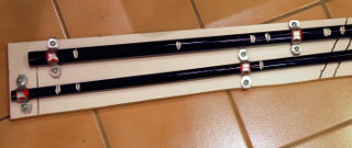
The antenna elements are made of 4 mm thick aluminum rod that is easily
evailable from hardware or hobby stores. (I could not easily find aluminum
TIG-welding wire, which also seems a popular material for Yagi elements.)
The antenna elements could maybe be packed inside the fishing rod for
transport, but it's a tight fit with the large number of 70 cm elements.
I bunch up the elements with rubber bands, and I'm looking for a suitable
fishing rod bag to transport them neatly. The whole thing weighs
xxx g, including guy lines and ground pegs.
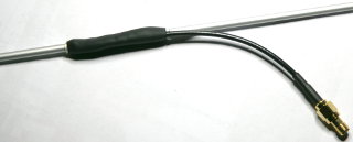
The single driven
element is in two pieces, isolated from each other with a short
piece of fiberglass tube, taken from the top section of the fishing
rod. A short coax pigtail with an SMA connector is soldered to the elements
with Alu-Sol 45D
aluminum solder (Sn/Pb/Ag solder with special flux for soldering aluminum,
stainless steel and some other strange materials; nothing smells
worse than the fumes from this solder, but it works!). The anodized surface
of the elements was first filed off to expose the bare metal. Then the elements
are epoxied into the fiberglass insulator, and the connection is
gooped up with hot glue and covered with heat-shrink tube.
|
|
To accurately drill the holes in the conical telescoping sections, I wrapped
electrical tape around them at several locations, so their diameters became
equal. I then clamped the sections onto a piece of board, and carefully
drilled through at the marked locations with a self-centering 4 mm
bit in a drill press. (Note that without
the electrical tape the conical shape of the telescoping section would have
left the elements at an angle.) I gooped the edges of the drilled holes
with cyanoacrylate (super glue) and filed them to a snug fit.
|
|
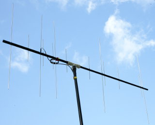
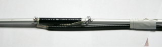
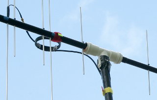
A plastic plumbing T-junction part serves to attach the Yagi boom to the
mast. The horizontal part of the "T" was lined with open-cell
foam inside, so the boom can just be inserted before the elements are
attached, and it is held in place by friction. It can freely be twisted
between horizontal and vertical polarization. The mast joins the
"T" with a through-pin to keep the antenna pointing where I
want it (this picture still has duct tape doing the job).
The elements have stoppers (cable ties) on
them, and are inserted through the boom from one side. A tight-fitting rubber
grommet is placed on each element to keep it in place (not strictly necessary
in vertical orientation, and thus missing from this picture).
The RG-58 feedline with a choke balun is attached
to the mast to relieve stress and connected to the coax pigtail of the
radiator element.
|
|
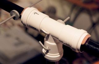
Here's the T-junction with through-pins securing it both to the mast and
the Yagi boom. Due to the radiator element's feedpoint construction, all the
elements are offset slightly from the boom, placing the whole thing a bit off
balance. Vertically this hardly matters, but horizontally a through-pin is
needed to keep it from twisting.
Note also the gray rubber grommets that hold the elements and
pins in place.
|
|
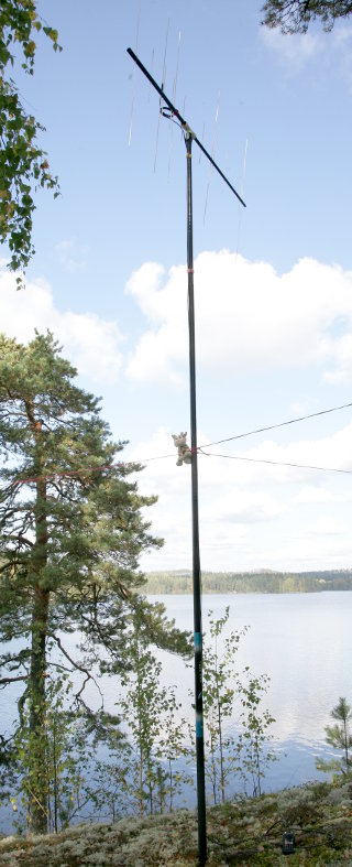
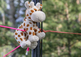
Three guy lines hold the mast up. These are tied or pegged at ground level
or in nearby trees. Since this is a
telescoping mast, locked only by friction, the guy lines should come at
quite a shallow angle. Otherwise any wind would cause the guy lines to
pull down hard on the mast, possibly causing it to collapse. If this were
a problem, through-pins could be fitted at each of the three joints in the
mast, locking it up securely. The guy lines are fitted loosely about
halfway up the mast using a helpful furry cow. It is at a safe distance
from the antenna, and unaffected by RF radiation. The loose fit
allows the mast and antenna to be rotated by hand.
|
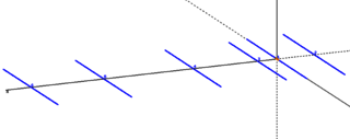
The 6-element 2 m Yagi is as compact as the dualband, and has less
elements to install when setting up. It also has slightly more gain on
2 m, and can also work on 70 cm in an emergency. I think it will
become my primary portable VHF antenna, but I'm keeping the dualband also.
Only the boom and elements are new for this antenna; all other parts are
shared between it and the dualbander.