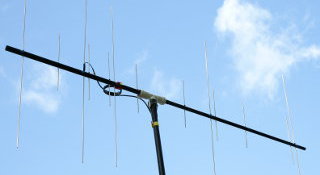
Here's some stuff I've built. Email me if you're especially interested
in some of them, if you need more detailed information, or if you
build a similar device for yourself.
A solid-state magnetometer to detect auroras
Auroras, or Northern lights, are cool. The Solar storms that cause them
also cause geomagnetic activity on the Earth. Thus a sensitive magnetometer
can be used to give warning of possible auroral displays.
I built a magnetometer using a Honeywell HMC1002 dual-axis
magnetoresistive sensor. An LM324 quad op-amp was used in a magnetic
feedback circuit (feeding into the offset-pins of the HMC1002)
to amplify
the signal, which was digitized by an Analog Devices AD974 A/D-converter
(a 4-channel, 16-bit, 220 kSPS direct-conversion device, total
overkill for this application), which interfaced with the parallel port
of an old 486 laptop. Data was read as fast as the parallel port could
serve it, and 1-minute averages were calculated and stored for later use
by Gnuplot.
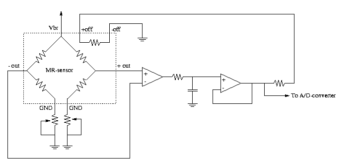
This circuit is very linear with respect to the magnetic field, and
extremely sensitive. It is also extremely sensitive to temperature
fluctuations, so just opening my front door in winter time looks like
a tremendous geomagnetic storm. Also no set/reset circuit is implemented,
which really should be done to maintain the sensitivity of the
magnetoresistive sensors over time. I'll try to find time to do that,
and to rebuild the analog section to make it less temperature sensitive.
For the time being, here are some sample
magnetograms measured with the above circuit.
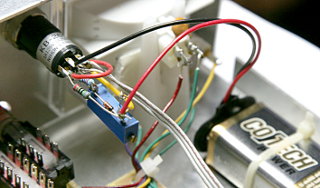
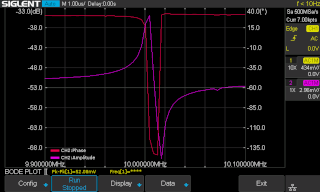
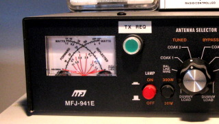
With this circuit, tuning is easy: Turn on the TX-Request, tune the
antenna, and turn off the TX-Request. Construction and adjustment of
the circuit were trivial, only drilling the mounting holes was somewhat
tedious, as I had to cover up the switches, air variable caps and other
stuff to keep the metal shavings out. Also, the vibration seems to have
broken the backlight bulb of the meter. I replaced it with a white LED.
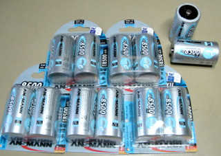
A discharge circuit for NiMH batteries
The Yaesu FT-897D transceiver can be fitted with two
FNB-78 13.2 V
4.5 Ah NiMH battery packs for portable operation. NiMH batteries
are great for this purpose, but they need to see regular use to stay
healthy. Mine aren't used that regularly, so I built a discharge circuit
which I could use to cycle the batteries every few months or so.
Here is the
schematic.
(Sorry there are no
component values. Figure them out yourself, or email me.) The circuit uses
a 12 V relay which powers its own coil until the battery voltage falls
below a certain threshold, set by VR1. At that point, the relay switches
off, disconnecting all circuitry from the battery. While the relay is
energized, regulator U2 draws a constant current from the battery, which
is simply lost as heat (the chassis of this device, taken from an old
AUI–10base2 Ethernet transceiver, is used as a heat
sink). A suitable power resistor would work just as well, but I didn't have
any on hand, so I used a regulator instead. A LED flashes on the discharge
device as well as on the radio, as the battery is being discharged.
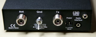
 I built a dedicated "Transmit Request" switch into the VersaTuner,
which interfaces to the ACC port on the back panel of the Yaesu
FT-897D.
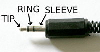
The ACC port is a standard 3.5 mm stereo jack, and it accepts a
negative-going ALC (automatic level control) signal on its tip
connection to allow an external device to limit the output power.
There is also a transmit-request signal on the ring connection,
which when grounded causes the radio to transmit a carrier for tuning purposes.
The sleeve is, of course, ground. I built a circuit which produces
an adjustable negative voltage (to set the transmit power) and activates
the transmit request on the radio. The switch also has a bright LED so
I can't leave it transmitting by mistake.
I built a dedicated "Transmit Request" switch into the VersaTuner,
which interfaces to the ACC port on the back panel of the Yaesu
FT-897D.
The ACC port is a standard 3.5 mm stereo jack, and it accepts a
negative-going ALC (automatic level control) signal on its tip
connection to allow an external device to limit the output power.
There is also a transmit-request signal on the ring connection,
which when grounded causes the radio to transmit a carrier for tuning purposes.
The sleeve is, of course, ground. I built a circuit which produces
an adjustable negative voltage (to set the transmit power) and activates
the transmit request on the radio. The switch also has a bright LED so
I can't leave it transmitting by mistake.