<HOME
<Electronics
<The bicycle

Modification of an HV9910B controlled LED light

Adjusting the brightness of an LED light for my bicycle

I'm using an Agena 800T LED light as the headlight on my bicycle. Its relevant specs are 9–60 V, 1×10 W, 800 lm, 6000 K, 60° beam, IP68. Power comes from a DIY pack of four 26650-size LiFePO4 cells, though an ordinary 12 V gel cell (SLA) battery would do fine as well. The lamp is fantastically bright when driving in darkness, but in the city it's just too bright. I only want to be seen (and to comply with the law), not to annoy (or even scare) people.

Therefore, modify the lamp. First I had to get inside it.

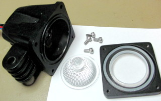
This lamp has four prominent Allen screws on the back of the housing, holding the lamp together. Once those were removed, the thing came apart easily (unlike some other LED lights, where the transparent plastic lens is glued onto the aluminum body). There are gaskets between the aluminum parts, the reflector and the lens, so the thing should be quite weatherproof despite the aluminum parts having a sizeable gap between them (wide enough to insert a piece of paper). Earlier I was considering sealing the gap with silicone caulk or something—not necessary!

The PCB contained the LED in the center, one hefty FET, some passives, and a GM9910BG controller IC. The datasheet was easy enough to find (another, more common name for the IC is HV9910B). Even before downloading that, I had identified what must be the current sensing resistor, as it was only 0.091 Ω. The light could be dimmed by increasing that resistance, but I wanted switchable brightness—and with a mechanical switch in the circuit, the contact resistances would easily be on the same order of magnitude.

The datasheet, however, offered two better alternatives: (1) muck about with the reference voltage at the LD pin that the current sensing resistor is compared against (in this circuit, LD is tied to Vdd and the controller is thus using its own internal reference), or (2) feed a PWM signal into the controller's PWMD pin (essentially an "Enable" pin, which is also tied to Vdd in this circuit). The latter seemed less hassle, and also that pin, being more easily accessible in the corner of the SO8 package, would be easier to lift off the PCB.

I removed the PCB from the lamp housing, revealing quite a workout waiting to be done. There's a feed-through rubber gasket at the back of the housing, where the power cable enters. I thought that was the weatherproofing for the lamp. But inside the housing, the entire back part had also been filled with epoxy to make absolutely certain the area around the gasket is completely watertight! So instead of just feeding slack cable through the gasket to get the PCB out for modification, I had to cut the wires going to the PCB. Then, to enable new wires to be installed, I had to drill out the epoxy-filled hole and fit it with a new gasket. Yes, this manufacturer does take weatherproofing seriously!

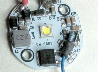
Once the PCB was out, I lifted pin 5 (PWMD) of the controller chip from the PCB. I then soldered a 7.87 kΩ pull-up resistor between it and Vdd (pin 6). Anything slightly below 10 kΩ should do according to the datasheet, even under any worst-case tolerance combination. Directly to the PWMD pin I soldered a wire which, when grounded, will turn off the LED, whereas when left floating, the LED remains on. By feeding it with suitable PWM, I could dim the intensity, which is what I wanted. I put a piece of heat-shrink tubing around the "loose" end of the resistor. Note that PWMD should be pulled high only to Vdd (which is internally regulated by the chip), not to the supply voltage! Going too far above Vdd will exceed the specifications of the GM9910BG and likely break it. So you want to have the pull-up resistor here inside the lamp, and have the PWM circuit (described below) only pull it down to ground.

Here's the circuit that I built to control the thing. It's a fairly common (if kind of "backwards") way to produce PWM with the classic old-school 555 timer (don't bother asking why I didn't use an Arduino instead), where the OUT pin provides the feedback for the astable timer, and the DISCH pin is instead used for output. Since DISCH is an open-collector output to GND (so it's either floating or grounded), it's ideal for controlling the LED driver as described above—it never pulls up to +12V, which might kill the GM9910BG controller. The frequency is about 600 Hz—high enough not to cause visible flicker, and the duty cycle can be adjusted from near zero to almost 100%. It could have been set with fixed resistors, but I wanted to find the desired brightness level of the LOW setting in real life.

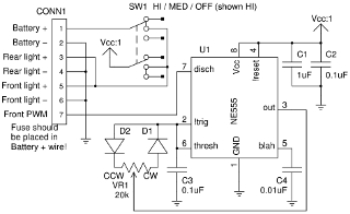
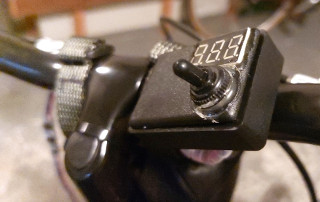
There is a 3-position "ON/ON/ON" double pole switch to select between HIGH, LOW and OFF. It switches the front light and the red rear light on and off, and in the middle position also activates the PWM circuit which dims the front light (see the schematic for the switch configuration). When the PWM circuit is unpowered, the LED shines at full intensity. Alternatively, I could have made the front light continuously adjustable by the potentiometer, but I really just wanted HIGH and LOW beams.

I did not want to go to the trouble of etching a PCB, so I used a scrap of veroboard and through-hole components instead of SMD. However, I was looking at a very small enclosure, and needed to make the board as small as possible, so I ended up placing the two diodes and several other connections on the reverse side—which is why that side side looks so ugly... There would actually be plenty of space in the box for a bigger circuit board, but I also wanted to fit in a cheap LED voltmeter from eBay, so that I don't inadvertently overdischarge the battery. That, the switch, and a feedthrough for the wiring left very little extra room.

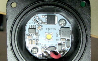
I reassembled the lamp housing, taking the PWM wire outside through the same hole used by the supply lead (which I had to replace, since I had just cut the original one). Not to fall short of the original weatherproofing, I also filled the back of the housing with epoxy like before, then reinstalled the aluminum-core PCB with new thermal grease (the PCB acts as a heat conductor from the LED to the housing).

The box containing the control circuit, voltage display and switch was attached to the bike's handlebars. I made some effort to weatherproof it, but I don't presume it to be nearly as watertight as the light itself. The switch, for example, is covered by a rubber sealing boot—designed to be screwed onto the switch, but of course the threads were not compatible, and I had to grind them away and glue the boot on instead. The box attaches to the handlebars with a clip I dismantled from a cheap bicycle bell.

A couple of wire connections are made out in the open, but properly sealed with hot-melt glue and heat-shrink tubing. Cable ties keep the wiring in place along the bike's frame. I used Powerpole connectors for the battery—these are not waterproof, but I try to keep them out of direct rain. A slow-blow 2 A fuse is in the power cord coming from the battery. The battery also has a 5-pole JST XH balancer connector.

I first considered using a 7 Ah SLA battery (sealed lead-acid, or "gel cell"), which is somewhat needlessly big, but it's what I happened to have on hand. With it I could burn the light at full power for four hours straight, while only using some 50% of the battery's capacity—that should be good for its longevity. Soon, however, I swapped it for a smaller DIY pack of four 3800 mAh LiFePO4 cells in series. Any battery will do, as long as the voltage is between 9 V (minimum for the light) and 18 V (maximum for the 555 timer).

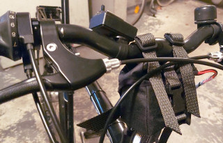
The LiFePO4 battery pack sits in a waterproofed Cordura fabric pouch attached to the handlebars. It is self-made, and waterproofed with a mixture of approximately 1:1 (by weight) of transparent sanitary silicone sealant and lamp kerosene (yes, really). These can be weighed into a jar and mixed by shaking for some minutes. The resulting goop can be simply painted onto the fabric with a brush and left to dry and set for a couple of days. While wet, the goop stinks to high hell, though—much worse than the silicone sealant alone!

Now that I finally have proper lights on my bicycle (including a red rear light, also required by law nowadays), I can safely say how dumb it was to pedal in the dark without them. And my headlight now has HIGH and LOW beams!  :)

However, stuff those flashing headlights somewhere where the Sun don't shine! You do not need that much extra visibility! Have you ever considered how much fun it would be, if everyone used flashing headlights??? Including cars??? Flashing lights should be for turn signals, emergency vehicles and warning signs only! So don't even think of decreasing the 555's frequency down to 4 Hz, or the ghost of Baron Karl von Drais will come to haunt you in the night!

The Agena 800T was reasonably cheap at IKH, and I think the same light (possibly under a different brand name) is sold at Motohelvete as well. It is very well made, weatherproof, and the body is aluminum, not plastic. There are cheaper alternatives as well, but if nothing else, they tend to be glued shut! The Agena was easy to open up for modification. Also its beam is a perfect shape for cycling, and it's a nice, compact, and rather stylish unit as well.


Antti J. Niskanen <uuki@iki.fi>