<HOME
<OH2GVB
<Electronics
Making a Bantam BC6-DC balancer adapter
 TL;DR? It's built like
this. But read on for
details.
TL;DR? It's built like
this. But read on for
details.
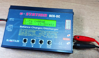
I use a Bantam e-Station BC6-DC to charge various battery packs,
including the low self-discharge NiMH pack
I use with my FT-897d when operating portable, the
internal LiPo batteries I used in the same
radio earlier, my bicycle headlight
battery, as well as the occasional other battery pack.
When charging individual cells, everything is simple. But when charging
multi-cell lithium packs, it's good practice to balance the cells at least
now and then. Otherwise a single cell that self-discharges a bit faster
than the others will lower the overall voltage of the pack, and the
charger will not cut off until the other cells are already in an
overcharged state. Or if a single cell begins to degrade and loses some
capacity, it will reach full charge before all the other cells, and will
become overcharged, likely degrading it even more.
Many battery packs contain a balancer circuit (and
other protection) built in, but e.g. RC hobby LiPo packs most often
don't. Instead, they have a balancer connector that allows compatible
chargers to do the balancing.
The BC-6DC has a balancer connector, but to actually connect a
battery pack's balancer connector to it, requires a small adapter board,
which is not included with the charger for some weird reason (or have I
just lost mine, I don't know). But the adapter is easy to make. The
connections are adequately explained on page 10 of the manual, with
examples shown of a 6-cell pack and a 3-cell pack.
It is also possible to connect two 3-cell packs or up to three 2-cell
packs in series, and charge them at the same time by using the balancer
function, as explained on page 21 of the manual. This requires a
special "Multi-adaptor" board (which is definitely not included
with the charger), whose connections are not explicitly explained, but
which are quite obvious.
|
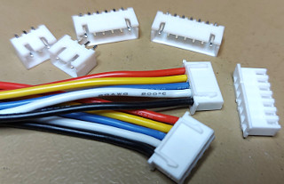
The connectors are "JST XH" connectors. For the
2–6 cell balancer board you need male connectors
(the ones with pins, which solder onto a PCB) with 3–7 pins,
one of each. If you want the "Multi-adaptor" functionality,
you will need two of the 4-pin connectors and three of the
3-pin connectors. In addition, you need an 8-pin female
connector (the one with holes, which you crimp onto wires, the one that
will plug into the BC6-DC).
Since I do not have a JST XH crimping tool (and using the wrong tool
is a pain and produces totally sub-par results), I wanted the 8-pin female
connector preassembled with wires. I could only find 5-pin females
preassembled, so I bought a couple of those, carefully dismantled the
contacts from their housings, and refitted them in an 8-pin female housing.
|
|
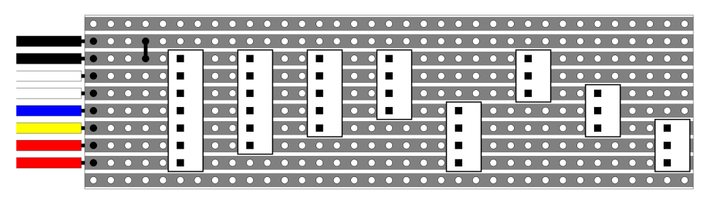
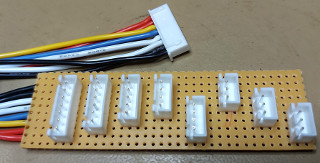
I built the thing on a piece of Veroboard measuring
10 strips × 35 holes. The picture should be
clear enough as to how everything is connected (click for
a bigger picture). Just
note that the picture is drawn from the component side of the
board, the copper strips are on the underside!
The female connector has two "ridges" on one side (so it cannot
be reversed when plugging it in). These ridges are upwards when the
board is component-side up. This is also the orientation in which it
plugs into the BC6-DC. The male connectors are all oriented
so that the slotted sides (where the corresponding ridges fit) are towards
the wired female connector end (i.e. to the left in the picture).
Note that the two black wires leading to the female connector are also
connected together! (Perhaps this is how the BC6-DC detects the presence
of the balancer board?)
|
|
Here's the completed adapter board. You would do well to protect the
underside against short circuits, but precisely how you want to do that,
I leave up to your own discretion.
Note that there is no magical color coding to the wires. The black ones
are the negative end of the battery pack, but after that I simply used
what wires I had available. I had five different colors to work with, as
I had disassembled two preassembled 5-pin wires to get the materials.
|
To use the adapter, just follow the manual: plug in the battery pack's
balancer connector to the board, plug in the board into the BC6-DC,
connect the main charging leads, and select the "BALANCE"
function and correct cell type and parameters. Only connect a single
pack at a time, and for 2 or 3-cell packs, use the connector nearest
the black wires' edge of the board (or nearest the wired female
connector), unless you're using the
"Multi-adaptor" functionality. If you are using that, only
connect identical battery packs which are approximately in the same state
of charge. You'll also need suitable wires to connect those packs in
series, but I leave that one up to you. I don't think I'll ever need
that functionality, but I built it into my adapter board just in case.
Do read the manual fully, be aware of the hazards of lithium batteries,
always verify you've selected the correct battery chemistry and charge
current, and never charge any batteries unattended. And don't blame me
if you do something stupid or if something else goes wrong! You have been
warned.
Antti J. Niskanen <uuki@iki.fi>