 Want to take a screenshot
over the GPIB bus?
Want to take a screenshot
over the GPIB bus?
Want to take a screenshot
over the GPIB bus?
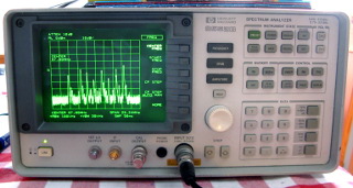
I once acquired a broken spectrum analyzer for free. There is absolutely no way I could afford to buy an analyzer like the HP 8562B, but it sure would be a useful instrument, so there was some incentive to try to repair it.
The problem in this instrument was that it did not display any signals, no matter what I fed it. Only the local oscillator's feedthrough signal was visible on the display at 0 Hz, and its level was too high, according to the service manual. After some testing of front-end components (attenuator and coaxial switch), some testing with the 0 Hz signal (its shape responds to the resolution bandwidth setting), and some reading of the service manual, I concluded the problem must be in the front-end mixer. No news here, that's where the problem always is in a spectrum analyzer.
|
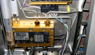
Opening up the instrument, the 1st mixer was immediately obvious. It is a dual-band mixer, which either upconverts low-band (0–2.9 GHz) signals to the 1st IF of 3.9107 GHz, or downconverts high-band (2.75–22 GHz, in five segments) signals directly to the 2nd IF of 310.7 MHz. Not having a signal generator for the gigahertz range, I could not test the high bands, but the low band (which is of more interest to me anyway) certainly was not working. |
|
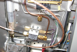
Here the replacement mixer is connected to the analyzer using whatever SMA jumper cables I had on hand. (Later I fabricated proper connections with semirigid coax.) The low-band input signal is fed into the mixer's IF port, the swept LO signal goes to the LO port, and the RF port feeds into the analyzer's 1st IF filter and second mixer. (The input and IF signals for the high bands are not connected anywhere, nor are the band-select and bias voltage lines, which originally connected to the Dual Mixer.) |
|
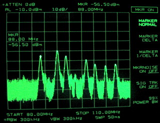
 With the new mixer, the analyzer's 300 MHz calibration signal could be
seen, surprisingly at a nearly correct amplitude as well. I then attached
an antenna, and could measure this spectrum from the FM radio broadcast
band. Several hours of playing with the instrument confirmed that it does
indeed work now. Its sensitivity is on par with the instrument's original
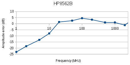
specifications, and frequency resolution is excellent. The frequency response
with the new mixer is, of course, not especially flat, but above 10 MHz it's
good enough to be useful, with an error of less than 5 dB (using my
E4421B as a reference). Amplitude
linearity is very good, of course. Perhaps I should look into calibrating
the analyzer over frequency—certainly the original mixer was no more
ideal than the Mini-Circuits one, so a calibration curve must be hidden
somewhere in the service menus.
But that's not a big deal anyhow. The main point is that now I can at least see
signals in the frequency domain and measure their frequencies, even if I
still cannot measure their amplitudes with any accuracy.
With the new mixer, the analyzer's 300 MHz calibration signal could be
seen, surprisingly at a nearly correct amplitude as well. I then attached
an antenna, and could measure this spectrum from the FM radio broadcast
band. Several hours of playing with the instrument confirmed that it does
indeed work now. Its sensitivity is on par with the instrument's original
specifications, and frequency resolution is excellent. The frequency response
with the new mixer is, of course, not especially flat, but above 10 MHz it's
good enough to be useful, with an error of less than 5 dB (using my
E4421B as a reference). Amplitude
linearity is very good, of course. Perhaps I should look into calibrating
the analyzer over frequency—certainly the original mixer was no more
ideal than the Mini-Circuits one, so a calibration curve must be hidden
somewhere in the service menus.
But that's not a big deal anyhow. The main point is that now I can at least see
signals in the frequency domain and measure their frequencies, even if I
still cannot measure their amplitudes with any accuracy.
|
Incidentally, if you want to get a screenshot from the 8562B (or possibly some other similar HP spectrum analyzer) over the GPIB interface, here's how. Although photos of the green display are much more cool... :)
The HP 8562B provides the 1st local oscillator signal on its front panel. This sweeps across 3.9107–6.8107 GHz, always 3.9107 GHz higher than the frequency being analyzed. By synthesizing a constant 3.9107 GHz signal and mixing it with the 1st LO signal, we get the sweep we want. That should be simple to synthesize with a PLL?
Two things: First, if your reference frequency drifts, your tracking generator drifts. That may be a problem when using narrower resolution bandwidths, down to 100 Hz, in the analyzer. 100 Hz in 3.9 GHz is only 0.025 ppm—crystals drift more than that! So your reference signal should be tied to the analyzer's time base—that way if it drifts, both the generator and the analyzer drift together. The analyzer's 300 MHz calibration signal, available on the front panel, fits this purpose perfectly. (Alternatively, both the spectrum analyzer and the tracking generator could share an external frequency reference.) Second, in case one of the IF filters in the analyzer isn't precisely where it should be, you'll want to be able to adjust the tracking generator's swept frequency by +/– a kHz or two with fine resolution.
If you download the manual for the HP 85640A tracking generator from the Keysight website (that's ex-Agilent), you'll see HP's own tracking generator used a chain of frequency multipliers and mixers to produce the 3.9107 GHz +/– something signal:
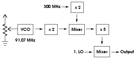
In its time, that may well have been a reasonable way of synthesizing the signal, but each frequency multiplier and mixer produces all kinds of artefacts, requiring extensive filtering as well (not shown in the figure).
Enter the modern high-resolution fractional-N PLL. The Analog Devices ADF4157 is a PLL with 6 GHz bandwidth (sufficient for our use), it can directly use the 300 MHz calibrator frequency as a reference (many other PLLs need a much lower reference frequency), and with its sigma-delta fractional-N interpolator it can generate frequencies with sub-Hz resolution, which are programmed via its digital 3-wire interface. With this fantastic device and a suitable VCO, the tracking generator comprises more or less the following (give or take a couple of amplifiers and attenuators):
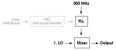
A single, programmable PLL that directly synthesizes the signal we need—that's simple enough for me to build! And that signal comes direct from the VCO, so it should be reasonably clean even without any filters. The PIC16F690 microcontroller is only used to program the ADF4157 to the desired frequency, so it's not really part of the signal path.
The ADF4157 only costs a few euros (plus considerable shipping expense, as I could not get it from any local suppliers). But surely all the frequency multipliers and mixers and filters would still cost more. (I've seen a HP 85640A going for 2000 euros.)
This project is still ongoing. Stay tuned (pun intended)...