<HOME
<OH2GVB
<Electronics
Behringer Eurorack MX2004A modification
Make the pre-Eq Insert connectors post-Eq
|
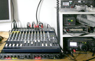
I have a Behringer Eurorack MX2004A mixer that will be used for
interfacing between my PC, broadcast radio tuner,
amateur radios, various microphones and my speakers.
For certain complex reasons, I'll want to use four of the mixer's
mono channels as independent microphone preamps with equalizers,
i.e. I want the amplified mic audio out of the box without
it going into the main mix. The Insert jacks can do this, but they are
pre-Eq. That is, the signal comes to the Insert jack before
going through the Equalizer. I wanted post-Eq Inserts.
Other people have done similar modifications,
converting
Inserts into post-Eq Outputs, but I also wanted to maintain
the possibility of injecting an audio signal back into the mixer.
Using four channels as mic preamps/equalizers
only leaves the AUX/Pan/Fader sections free to be used e.g.
as two extra stereo input channels—albeit without Eq. Thus I wanted
to keep the Insert as an Insert, not change it to an Output only.
Thus: Modify the mixer my own way. :) I had already performed
a custom modification on
my Eurorack UB502 mixer to change the way its
headphone volume control works (and later I did that same mod to my
t.Mix MIX802).
This mod turned out to be quite simple
as well, requiring very few parts (two capacitors and one resistor
per channel), but it did require major
disassembly and reassembly of the mixer, which was not an easy task!
|
|
|
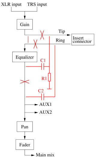
This (much simplified) block diagram shows how a mono input channel is wired
in the MX2004A. Note that AUX1 is switch-selectable as pre- or
post-Fader (shown pre-Fader here), whereas AUX2 is usually hard-wired
post-Fader. However, I also modified AUX2 on the mono channels
1–8 to be pre-Fader,
as per the manufacturer's instructions on page 24 of the
User's
Manual.
The Insert modification I wanted to perform
is shown in red: Basically isolate the Insert jack,
bypass it, then cut the signal path after the Eq and insert the Insert at
that point.
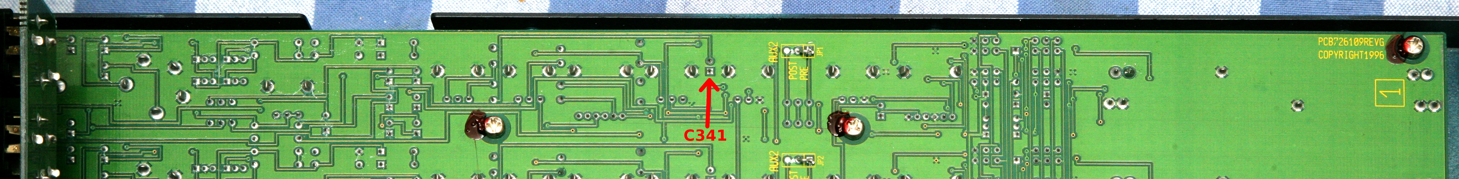
Looking at
the
schematic for mono channel CH1, it's immediately obvious that
C341 is the ideal new location for the Insert. Removing that
capacitor from the circuit board neatly cuts the signal path right after the
Equalizer, and wires going to the Insert jack are easy to attach there.
Note that a similar capacitor must be provided in the modification
(C2 in the diagram), and
good form requires duplicating the output network (C161 and
R302; or C201 and R301) that the original Insert jack
had—thus the extra R1 and C1 in the diagram.
Parts needed per channel:
C1, C2 = 100 μF 25 V
R1 = 20 kΩ
bits of wire
heat-shrink tube
hot-melt glue
|
To open the chassis, remove four screws from both sides (but not the ones
holding the plastic front part).
Then turn the mixer upside down, and open the three screws
at bottom front, and three at bottom back (but not the two recessed ones
in the area that gets hot during use). Now lift up the
bottom half of the chassis, front-side first, being careful not to yank
off the wires going to the power supply module, which is mounted on the
bottom.
Removing the main board from the chassis is a pain,
as you need to pull off
all of the 97 potentiometer and 15 Fader knobs, and all 50
pushbutton hats, unscrew all 25 phone jacks on the top side,
and remove all the retaining screws from the
top-side XLR jacks and RCA connectors. Finally remove all 26 screws
holding the main board (from the circuit board side, not from the top side).
You'll also have to remove the rear connector
board, so unscrew its phone jacks and XLR connector screws as well.
Also be warned that getting the main board back in place will be
a major pain! You may want to learn a couple of new swear words
before you begin.
|
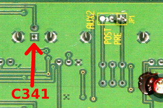
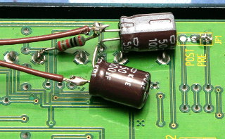
This is the location of capacitor C341
(see the full image)
for CH1. The square pad is negative, the round pad is positive.
Remove it, and clean up the pads with desoldering braid. This cuts the
connection between the Equalizer and the Pan control. Do the same
for all other channels you wish to modify. The
corresponding capacitors (C342...C348)
for the other channels are in similar locations,
as all eight mono channels are identical.
If you're only modifying some of the channels, you might still want
to remove that capacitor from all channels, and install the same
type of capacitor on the other side of the board! That way, if you
ever want to modify the rest of the channels, you won't need to
remove the board again! Unfortunately I thought of this only after
reassembling the mixer. :(
|
Now the circuit board can be reattached to the chassis. All the potentiometer
shafts can be surprisingly difficult to align to their corresponding
holes, not to mention all the phone jacks! The thread surrounding the
jack gets caught on the edge of the hole in the chassis, making the
operation darn near impossible! How the fsck do they do this at the
factory??? Once things begin to fall into place, insert a couple of screws to
hold the circuit board. Now wiggle the jacks one at a time to
try to get them seated properly. Remember to swear a lot.
Loosely attach locking nuts to the jacks
whenever possible, to prevent them from slipping out again. When almost
done, remember to wiggle the XLR connectors to align them properly also,
instead of just tightening everything down with force.
When everything is properly seated, attach and tighten all the screws
holding the circuit board and the XLR and RCA connectors,
and tighten the locking nuts on all jacks. Then reattach the rear connector
board. Now you can also
reattach the potentiometer knobs (don't you wish you had somehow made note
of which color knob goes where?), Fader knobs and pushbutton hats.
(Note: A single trace is seen going from C341 towards the
Eq section, suggesting that disassembly of the circuit board from the
chassis might not be required—instead of removing the capacitor
to break the signal path, simply cut that trace. However, that will
not work, for there is another trace leading from
C341 on the other side of the board! Sorry.)
|
 Now assemble the new output network
consisting of C1 and R1 (see the above block diagram),
and the input blocking capacitor C2 (ditto):
Solder the positive leg of C1 to the positive (round) pad
on the circuit board, where C341 used to be.
Solder one end of R1 to the other leg of
C1. Solder the other end of R1 to ground—that's the
big solid areas of the PCB. Any convenient grounded point is fine, I used
a joint where the case of one of the potentiometers was soldered to the
ground plane. Connect the negative end of C2 to the negative
(square) pad on the circuit board. Two wires will go from these components
to the Insert jack on the back panel.
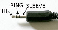
Attach one wire to the point between C1 and R1—this
wire will go to the tip terminal of the jack (see below).
Attach the other
wire to the unconnected leg of C2—this will go to the
ring terminal of the jack.
Now assemble the new output network
consisting of C1 and R1 (see the above block diagram),
and the input blocking capacitor C2 (ditto):
Solder the positive leg of C1 to the positive (round) pad
on the circuit board, where C341 used to be.
Solder one end of R1 to the other leg of
C1. Solder the other end of R1 to ground—that's the
big solid areas of the PCB. Any convenient grounded point is fine, I used
a joint where the case of one of the potentiometers was soldered to the
ground plane. Connect the negative end of C2 to the negative
(square) pad on the circuit board. Two wires will go from these components
to the Insert jack on the back panel.
Attach one wire to the point between C1 and R1—this
wire will go to the tip terminal of the jack (see below).
Attach the other
wire to the unconnected leg of C2—this will go to the
ring terminal of the jack.
Do the same for all other channels you wish to modify.
|
|
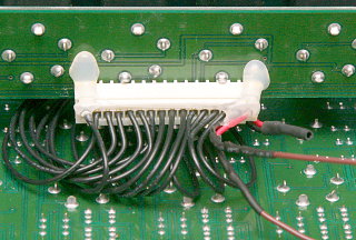
The Insert connectors are on the rear connector board, and they are
connected to the main board via the 16-pole connector with one red and
15 black wires. Beginning at the red wire,
the wires are CH1 ring, CH1 tip,
CH2 ring, CH2 tip,
and so on. For each channel you wish to modify, cut both wires, and
connect the ones going to the main board directly together. This bypasses
the Insert connector between the Gain and Eq stages. Do this one wire pair
at a time, or you will lose track of which is which.
Now connect the tip and ring
wires coming from your
C1 / R1 / C2 assembly to the
corresponding wires going to the rear connector board. This restores
the connection between the Equalizer and the Pan control through the
Insert jack, thus completing the modification.
Cover up your connections with heat-shrink tube.
The photo shows one channel (CH1) already modified.
|
|
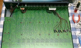
I modified four of the eight mono channels
on my mixer. When done, I gooped up the
capacitors with hot-melt glue to make sure they don't shake around creating
short circuits, and bunched up the wires neatly.
Make sure you leave no bits of wire anywhere to cause shorts. Nor should
you leave any stripped insulation or other garbage
rattling around inside the mixer, or you'll never get
peace of mind...
Reassemble the mixer and test it. If all has gone well, the
modified Inserts are now post-Eq. Any unmodified ones should work
just as before (i.e. pre-Eq). The audio levels (both input and
output) of the modified Inserts should be the same as before modification.
No other features of the mixer should be affected at all.
And, for the record, this modification works the same, whether or not you've
performed the AUX2 mod.
|
On the other hand, if you did manage to break something in the course of
your attempted modification, you now have
a broken mixer, congratulations!
So don't attempt this modification unless you
know what you are doing and are willing to take that risk,
and in any case don't blame me for anything
bad that happens!
Antti J. Niskanen <uuki@iki.fi>