<HOME
<Electronics
Behringer Eurorack UB502 / Xenyx 502 modifications
Make the headphone volume
control independent of the "Main mix" fader
Change the "Tape out" into a pre-fader
"AUX" microphone output
Make the 6.3 mm TRS mono input compatible with
headset condenser microphones
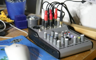 My PC sound card is connected to my Genelec 1029A speakers, both of which
have their own independent volume controls—so adjusting volume using
those is somewhat inconvenient. Using a software volume control app is even
more inconvenient. So I'm using a small mixer to control the volume, and
also as a headphone amplifier. Using headphones with my computer would be
completely impractical otherwise. Originally I used a second-hand
Behringer UB502, which was fine for this purpose except for one
thing: the headphone
amplifier with its own volume control is post-fader—so
the mixer's "Main mix" fader also affects the headphone
volume. I'd like to be able to completely silence the speakers on the
main output, yet adjust the headphones with their own volume control.
Thus: Modify the mixer. On day one after the
purchase. :) I have subsequently done this same
headphone mod to my t.Mix MIX802 and my
Behringer MX802A as well.
My PC sound card is connected to my Genelec 1029A speakers, both of which
have their own independent volume controls—so adjusting volume using
those is somewhat inconvenient. Using a software volume control app is even
more inconvenient. So I'm using a small mixer to control the volume, and
also as a headphone amplifier. Using headphones with my computer would be
completely impractical otherwise. Originally I used a second-hand
Behringer UB502, which was fine for this purpose except for one
thing: the headphone
amplifier with its own volume control is post-fader—so
the mixer's "Main mix" fader also affects the headphone
volume. I'd like to be able to completely silence the speakers on the
main output, yet adjust the headphones with their own volume control.
Thus: Modify the mixer. On day one after the
purchase. :) I have subsequently done this same
headphone mod to my t.Mix MIX802 and my
Behringer MX802A as well.
I later did another modification to this mixer, to
provide an "AUX send" of sorts. For teleconferencing with a
full headset on, I find it necessary to mix a tiny bit of my own microphone
audio into what I hear from my headset—without it, the damping of
my own voice (compared to how I hear myself without a headset) makes
speaking totally unnatural and uncomfortable. I already modified
another mixer to make its AUX send pre-fader,
so I can route my mic audio through the mixer, take it into the PC's
soundcard input via the AUX send, and decrease the mic channel's fader
down to a very low level. The UB502 has no AUX send, but it was
surprisingly easy to hack one up!
Finally, along with the "AUX send" mod, I did
a third modification to make the mic input
compatible with typical PC headsets, which have condenser microphones that
require a "bias voltage" to work.
The headphone volume modification
|
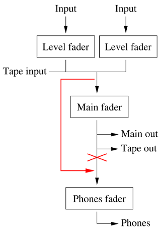
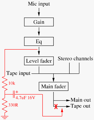
This (much simplified) block diagram shows how the UB502 is wired
internally. You can see that the headphone amplifier is controlled by
both the Phones fader and the Main fader. The mods
I wanted to do are shown in red: Basically bypass the Main fader
from the headphone amplifier's input.
That would provide two independent volume
controls: one for controlling my stereo amplifier, one for the headphones.
I found
the
schematic for the Behringer Xenyx 502 online,
and it seems to be identical to what I found inside my mixer—all the
component values and their reference numbers were the same. If you
look at the schematic's sheet 2, you see the headphone amplifier
circuit gets is signal from switch SW1A/SW1B (the
"Tape to phones" switch).
It selects either the tape input directly (with the switches in the
down-position), or the mixed signal, post-fader (with the switches in the
up-position, as drawn on the schematic).
I decided to take the signal for the SW1A/SW1B up-position from
elsewhere in the circuit, before the
"Main mix" fader. I decided a good place to take the signal
would be between C42 and R77 (for the left channel, to
SW1A) and between C43 and R90 (for the right channel,
to SW1B). But first I must isolate those terminals of SW1A
and SW1B from the rest of the circuit.
|
To isolate the switch, you must cut four traces in the circuit board. To
access the proper places, you need to completely remove the circuit board
from the chassis. First pull up all the various potentiometer knobs (they
are only friction-fit and will come off by pulling only). Remove the six
screws on the bottom of the chassis (remember which ones go where!) and
pull off the bottom panel. Remove the four screws on the sides of the
mixer and remove the plastic side panels. Remove the two screws around
the XLR connector, the one in the middle of the four tape in/out
RCA connectors, and the two near the front of the mixer. Finally
remove the nuts and washers holding the eight 6.3 mm phone jacks in place,
and remove the circuit board.
|
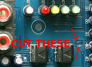
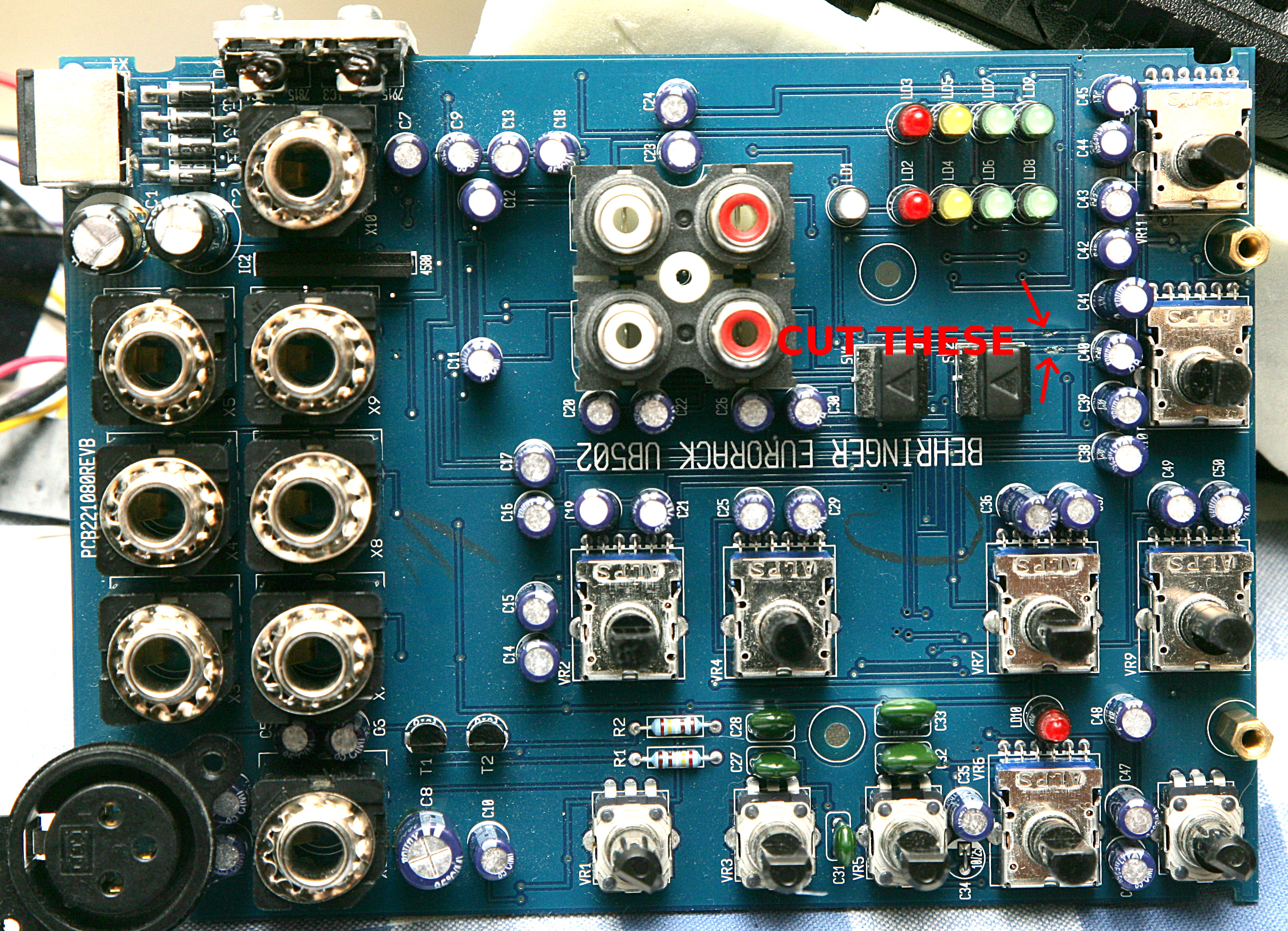
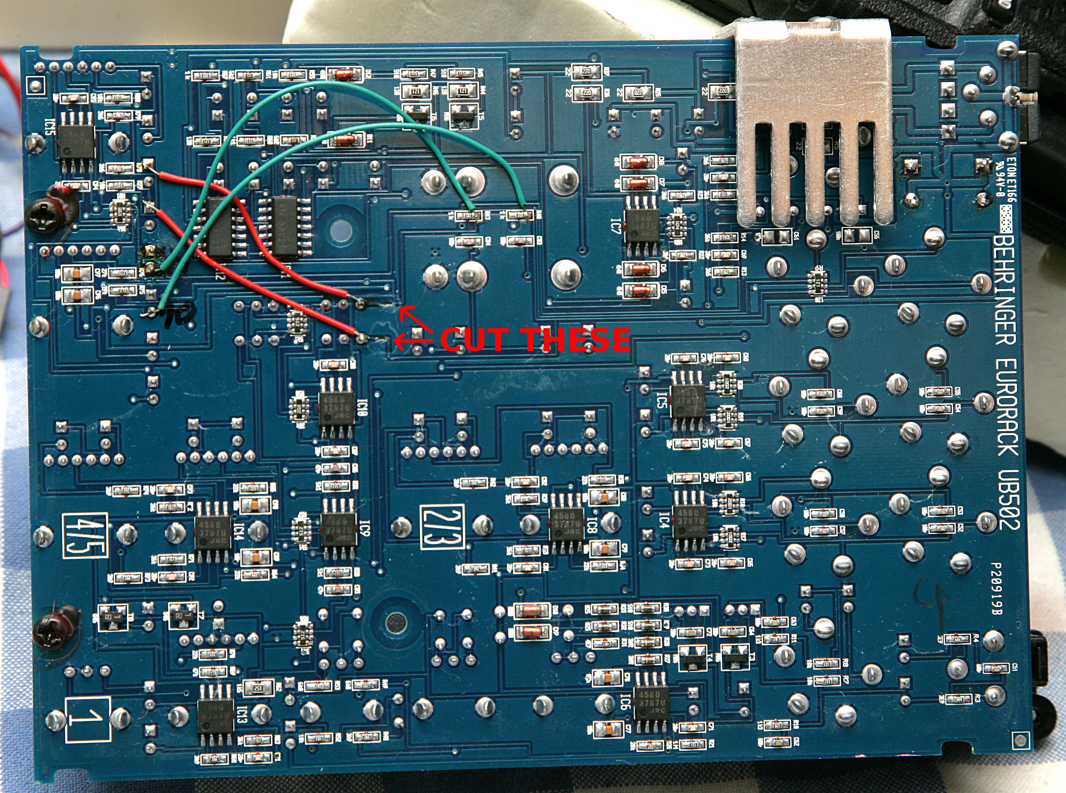
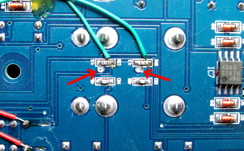
On the top side of the board, cut two traces as shown (see the full
image here). The ones you want to
cut are the top and bottom one in that bunch of four. Try not to damage
the adjascent traces (as I almost did). When cut and cleaned up, I put
a drop of cyanoacrylate superglue on the area for no special reason.
(Well, it might protect the traces I scratched by accident from corrosion,
but the traces I intentionally cut obviously don't need any protection.)
I cut the traces with a sharp snap-off knife, but I've later learned that
a Dremel-type mini drill with a small milling bit is a lot easier and
more controllable.
|
|
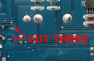
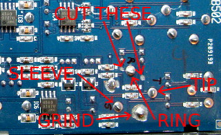
On the bottom side of the board, cut two more traces as shown (see the full
image here). The ones you
want to cut are the ones going to the two rightmost pins of the switch.
I likewise covered these areas with cyanoacrylate.
|
|
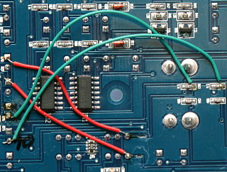
This has isolated the required pins of the switch, but has also cut the
circuit it was connected to in half. Two jumper wires must therefore be
soldered in place on the bottom side of the board (the green ones in the
image, see the full image here).
One wire goes from the positive terminal of C40 to the right-hand
end of R40 (when viewing the board as shown in the picture). The
other wire goes from the positive terminal of C41 to the right-hand
end of R43. Both R40 and R43 are SMD resistors, but
it's entirely possible (if somewhat tedious) to solder wires to them.
With this done, no signal at all goes to the headphone amplifier when
"Tape to phones" is not selected, but the
"Main out" works as before, as do the
"Tape to phones" and "Tape to mix"
switches.
Finally, to connect the isolated terminals of the switch to the
pre-fader main mix signal, solder another two wires (the red ones). One
goes from the negative terminal of C42 to the lower-right pin of the
switch. The other goes from the negative terminal of C43 to the
upper-right pin of the switch. These are all through-hole components and
easier to solder to. This essentially parallels the headphone
amplifier section (when "Tape to phones" is not
selected) with the main mix fader and Main out section, completing
the modification.
|
When soldering the jumper wires, make sure you don't short-circuit them
to any other nearby components or board traces. And while you're inside the
mixer, you might consider replacing the power supply filter capacitors
(C1 and C2, both are 470 μF 35 V
electrolytics. Use 105°C ones, preferably low-ESR type if you have
them in-shelf, but ordinary ones are fine too). One of them was
visibly swollen on my unit. This is the first time I have ever seen
swollen capacitors on a linear power supply! On SMPSs they are
an everyday nuisance, but to start failing on a linear supply they really
have to be cheap!
Reassemble the mixer and test it. If all has gone well, you can now
control the main and tape outputs with the "Main mix"
volume control, and
the headphone output with the headphone control, independently!
The "Tape to phones" and
"Tape to mix" switches work exactly as before. The level
indicator LEDs, however, are now pre-fader also, so they keep blinking along
with the mixed signal even if the "Main mix" fader is
turned down to zero. But blinking LEDs are nice—why should they turn
off just because the music is silenced? Ok, maybe they're not useful
anymore for adjusting
levels when mastering a musical recording, but I'm not using this mixer
for mastering anyway.
The "Tape out" to "AUX send" modification
|
This shows a simplified block diagram of the microphone input, the
RCA "Tape out", and the modification I wanted to do.
Looking at the
schematic,
the negative end of C35 would be the perfect place to take the post-Eq,
pre-fader CH1 (microphone) signal. This is a line level signal (it's after
the mic preamplifier), and my ultimate intention is to feed it into the mic
input of a PC sound card, so an attenuator will be needed. By building that
attenuator inside the mixer, I could be sure of not loading the internal CH1
audio line too much under any circumstances, even if the output is shorted.
Thus there was no need to add a buffer stage, and I could just connect the
attenuator's output directly to the "Tape out".
I have never had use for the unbalanced "Tape out", because the
balanced Main output can be used as an unbalanced output just as well. I
could have added a new connector for this mic-level "AUX"
output, but that would have involved drilling a new hole in the chassis.
Too much bother, and too ugly!
The resistor attenuator lowers the line level signal to mic level, suitable
for most PC sound cards, and the capacitor blocks any "bias
voltage" the sound card might provide for an external microphone.
I made two separate circuits, to connect to the two RCA outputs, one with
the component values shown, the other with a
1 kΩ resistor instead of the 10 kΩ. This lets me
choose the more suitable output level as needed (there's no AUX level
potentiometer, of course, so I can only choose one or the other output,
and fine-tune the mic gain in the PC). One could also make both
attenuators identical, and connect two PCs, or a PC and a phone, to the
same mixer. But if I ever do need to do that, I'll just use a
bigger mixer with two proper AUX sends.
|
|
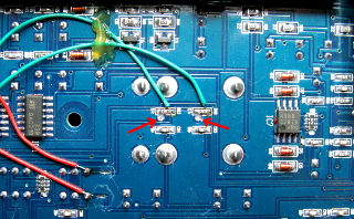
To isolate the "Tape out" connectors, I cut the traces leading
to them from R40 and R43.
The traces go to vias immediately beside the resistors, which made cutting
them a bit delicate. These would have been a pain to cut with a snap-off
knife, but with a mini drill and a tiny milling bit, it was easy enough
to do under magnification. See a close-up photo
here. Longer traces, easier to
cut, would be available on the opposite side of the
board, but I just couldn't be bothered to remove the PCB, which would require
pulling all the potentiometer knobs, removing all the retaining nuts from all
the jacks, etc. Not to mention the pain of reassembly.
The red and green jumper wires you see in the photo are from the earlier
headphone volume modification. Yes, the green ones also
go to R40 and R43, which are isolated here, but to their
opposite ends. This modification will work the same whether or not you've
done the headphone mod.
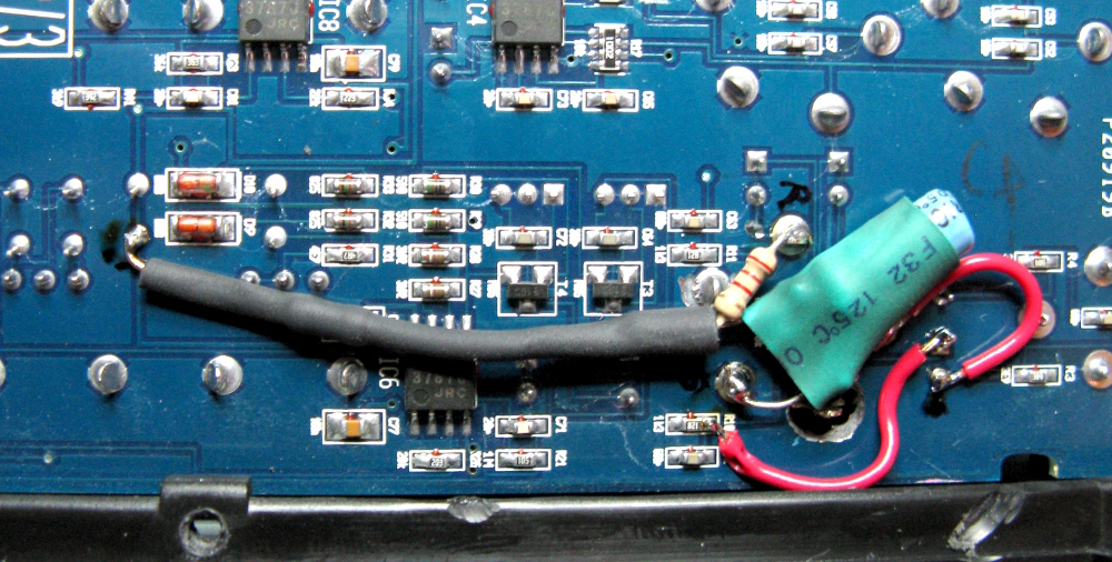
|
|
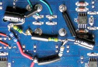
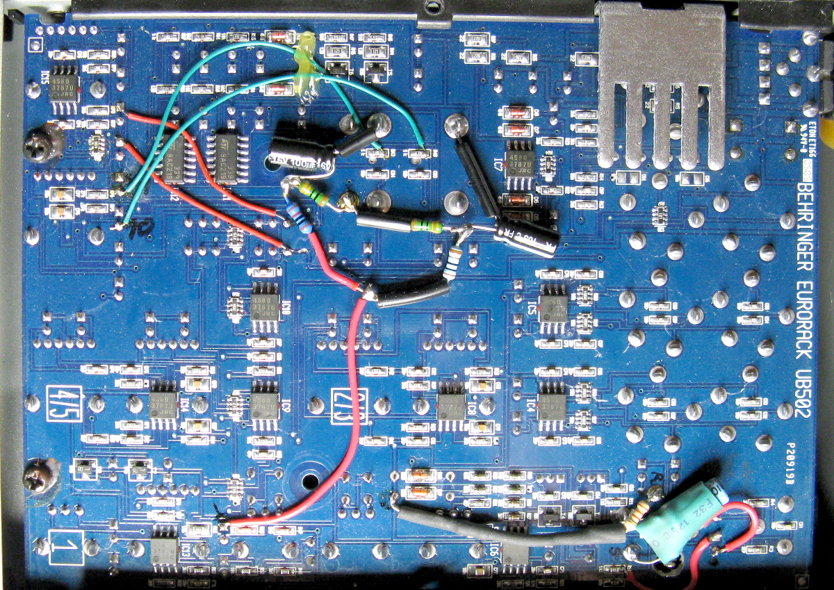
Then I soldered the necessary resistors and capacitors "ugly style"
onto the RCA jacks' legs, and wired them to C35. Bits of insulation
stripped from wire are inserted onto the longer component leads in order to
help avoid shorts. I finally applied some hot glue to help
keep everything in place, and to ensure there'll be no shorts to the chassis.
See a photo of the full PCB here.
(All the garbage in the lower right corner is from the mic
input mod below.)
|
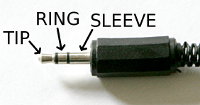 To connect this output to a PC's sound card input, you just need an RCA
to 3.5 mm cable. A mono one will do, if your sound card has separate
headphone out and mic in jacks. However, if you have a 3.5 mm
TRRS (4-terminal) mic/headphone combo jack, you'll also need a
"TRRS-CTIA" adapter to split it into two separate jacks, and
with that adapter, you'll need a specially connected stereo
3.5 mm plug in the RCA cable. That's because the
"TRRS-CTIA" adapter tries to mimic a typical sound card mic
input (described in the next modification), and
connects the mic line (with bias and all) to both "TIP" and
"RING" of the jack. Plugging in a mono plug would short
"RING" to "SLEEVE", which is ground, thereby shorting
"TIP" to ground as well. So you'll need a cable where the RCA
center pin is connected either to "TIP" only, or to both
"TIP" and "RING". The RCA outer contact should be
connected to "SLEEVE", of course. (In an emergency, you can use
a stereo 3.5 mm to 2× RCA cable: plug the left RCA
into the mixer, and leave the right RCA unconnected.)
To connect this output to a PC's sound card input, you just need an RCA
to 3.5 mm cable. A mono one will do, if your sound card has separate
headphone out and mic in jacks. However, if you have a 3.5 mm
TRRS (4-terminal) mic/headphone combo jack, you'll also need a
"TRRS-CTIA" adapter to split it into two separate jacks, and
with that adapter, you'll need a specially connected stereo
3.5 mm plug in the RCA cable. That's because the
"TRRS-CTIA" adapter tries to mimic a typical sound card mic
input (described in the next modification), and
connects the mic line (with bias and all) to both "TIP" and
"RING" of the jack. Plugging in a mono plug would short
"RING" to "SLEEVE", which is ground, thereby shorting
"TIP" to ground as well. So you'll need a cable where the RCA
center pin is connected either to "TIP" only, or to both
"TIP" and "RING". The RCA outer contact should be
connected to "SLEEVE", of course. (In an emergency, you can use
a stereo 3.5 mm to 2× RCA cable: plug the left RCA
into the mixer, and leave the right RCA unconnected.)
The microphone input modification

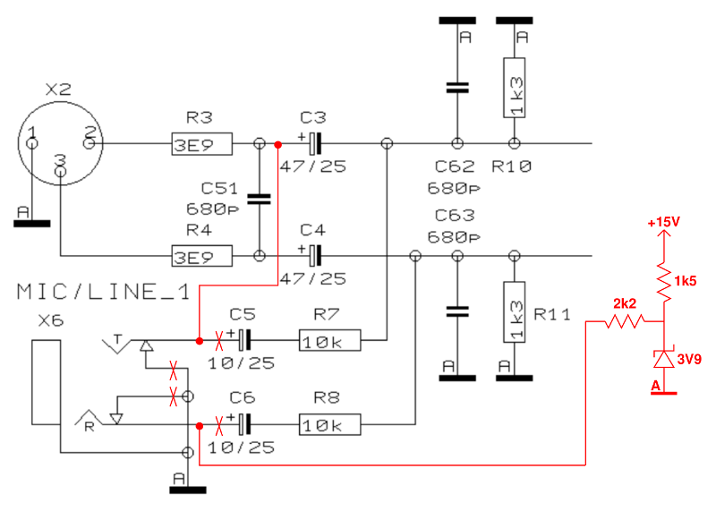
|
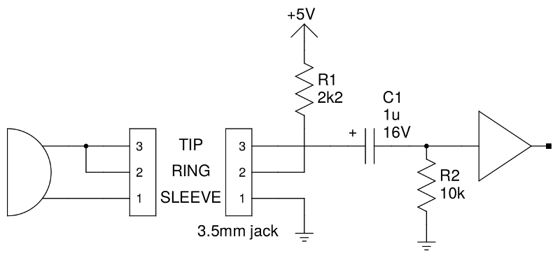
A dynamic microphone can be plugged directly into the mixer's mic input,
of course. A typical PC headset's condenser microphone, however, needs
a "bias voltage", typically provided as shown
here. That's
very different from the 48 V "phantom voltage" used in
professional microphones, by the way! And this mixer does not provide
phantom power on its mic input anyway.
|
|
Since CH1 is a single mono input, I don't think I'll ever be connecting
a line source to it. So I decided to convert its line-level 6.3 mm TRS
jack into a mic input that mimics an unbalanced PC sound card
microphone input, with the necessary bias voltage.
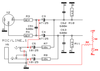
Here is an excerpt of the
schematic, with my modifications shown in red.
Firstly, the "TIP" and "RING" contacts of the jack,
and the "TIP" contact's switched terminal as well, are isolated.
The switched contact will not be reconnected anywhere, as I want
"TIP" of the jack floating when no plug is inserted.
Secondly, the zener diode, resistor and capacitor provide a stable
3.9 V bias voltage into the "RING" contact through the
2.2 kΩ resistor. Finally, the "TIP" contact is wired
directly to the positive end of C3, which places the mic signal onto
the "HOT" line (pin 2) of the XLR connector, while the
"COLD" line (pin 3) remains grounded through R11.
When nothing is plugged into the TRS jack, this does not affect the XLR
input in any way, and a dynamic XLR microphone can be used as usual.
Since nearly all electret microphones will connect "TIP" and
"RING" together, the DC bias voltage will be present also on the
mic input signal, but C3 will conveniently block that from the
following amplifier stage. If an unbalanced dynamic microphone is plugged
in, its mono plug will short the bias voltage to ground (no matter, the
2.2 kΩ resistor limits current) and its audio signal will be
fed into the XLR's "HOT" line as usual.
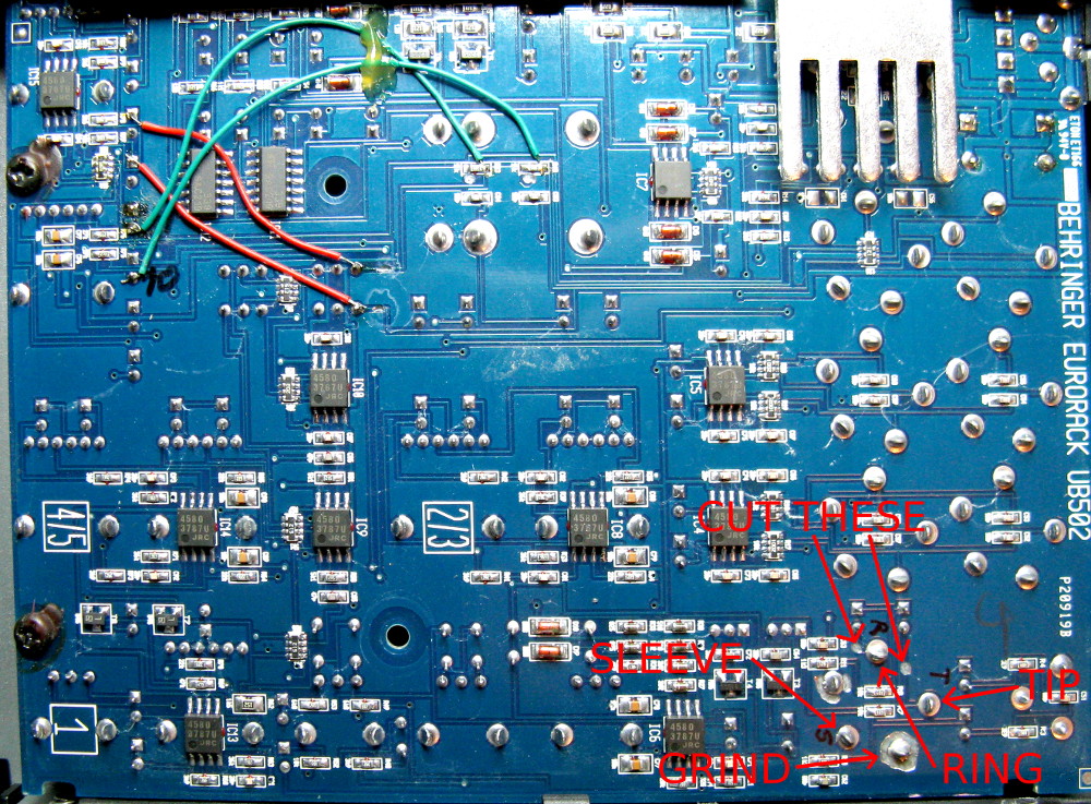
|
|
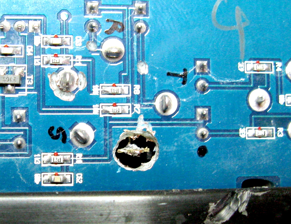
To isolate the "TIP" and "RING" contacts, I simply
cut the two traces leading to them. Isolating the switched contact, however,
was a pain. I first ground away the copper all the way around the solder
joint, but that did not isolate it! Apprently there's a ground plane on the
front side of the board as well. Since the connector body itself would be
in the way, I wouldn't be able to do the same on the front side, so I went
ahead and ground all the way through the circuit board from the
back side! See a bigger photo of the whole board (not yet ground through)
here, and see a picture of the
completely ground through solder joint
here. Yes, that's your basic
circuit modification! :)
I had already tried to isolate the switched contact of "RING" as
well (you can see that in the above
photo; that cut did not isolate
it either), but luckily I realized that that
switched contact does not need to be isolated after all. It would have
been a lot more difficult to grind, as it's so close to an SMD resistor.
(I had already slipped once, and inadvertently cut through one trace
while grinding out the "TIP" switched contact, so who knows how
much damage I would have caused.)
An alternative to grinding the board like that would be to leave a stereo
6.3 mm–3.5 mm adapter permanently in the jack, even when
using the XLR input. That disconnects the "TIP" contact itself
from its switched contact. But it's not as elegant a solution.
|

|
I then wired the "TIP" terminal (mic signal input) to the
positive end of C3 (and soldered a jumper wire to fix the damage
I had caused by accident), and connected my circuit (with the two resistors,
capacitor and zener, soldered together "ugly style" and covered
with heat shring tube) to the "RING" terminal (bias voltage
output) and "SLEEVE" terminal (ground) of the jack, and to
R1 (+15 V), as shown
here. Looking at the schematic,
you should be able to deduce which of the red wires is part of the
modification, and which just fixes the destroyed board trace when my
hand slipped while drilling...
Knowing the locations of various components on the front side of the board
(from the photo I took during my
first modification with this mixer), these latter two modifications were
possible without having to remove the board from the chassis.
|
With all the modifications finished, I can plug a headset into the headphone
output and its microphone into the CH1 TRS input with nothing more than
6.3 mm–3.5 mm stereo plug adapters. Then I plug my
"TRRS-CTIA" adapter into my laptop, connect its mic input to
the "Tape out" RCA connector as described in the previous
modification, and its headphone output to the CH2/3 stereo input with a
3.5 mm stereo to 2× 6.3 mm mono cable. Now I adjust
the headphone audio as usual (by adjusting the PC's output level, CH2/3
fader and headphones volume. While speaking into the microphone, I adjust
CH1 gain and the PC's software mixer so that the volume is correctly set
in the PC. Finally, I increase the CH1 fader until I hear just enough of
my own voice in the headphones to make speaking feel natural with the
headset on.
A word of warning
Nothing described here is especially difficult to do, but does require
some skill in soldering and a steady hand when cutting traces. Also it's
entirely possible that you have a different revision of the mixer, with
a different layout in the circuit board, or with different reference
designators for the components. Before making any changes, please check
that your PCB is consistent with my instructions.
Do not attempt this modification unless you
know what you are doing and are willing to risk breaking your mixer,
and in any case don't blame me for anything
bad that happens!
Antti J. Niskanen <uuki@iki.fi>