<HOME
<Electronics
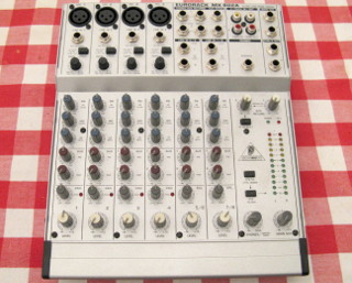
Behringer Eurorack MX802A modifications
Make the "Phones" volume control
independent of the "Main mix" fader
Make all the AUX sends pre-fader
Add a "Natural Crossfeed Mixer" to the
headphone output
Bad power supply capacitors
|
One might think I do this headphone volume modification for a living...
This is the third mixer I've modified this way! That's the result
of upgrading and upgrading and upgrading whenever a nice mixer comes
my way with a good price tag. If you wish to read
a preamble as to why I want these mods, or how the mods work
on a general level, please see my pages on the
t.Mix MIX 802 and the
Behringer UB502. On this page I'll
just get straight to the details of how these mods are performed.
So far, Behringer mixers have been especially nice to modify, because you
can easily find online both the user manuals and the complete
schematics for most mixers. However, what I found inside this MX802A
(with the main board marked "MX802A/01" and
"PCB908039REVG") absolutely did not correspond to
the schematic I found—which did say only "MX802"
in its title block, without the "A" suffix. Probably the
function of the mixer follows the schematic, but component values
might differ, and their reference designators definitely do!
Therefore, please do not blindly trust any component reference
designators that I mention on my web pages! It is entirely
possible that they do not correspond to the circuit board inside your
device! First follow the traces on the board to ensure the component
in question is the correct one in relation to other components! The
designators I mention in the following are what I found on my board.
|
|
Opening the mixer
If you want to remove the main circuit board, you will firstly need to
pull off all the potentiometer knobs except the "Gain" knobs on
the four Mic inputs. Yes, there's 46 knobs to remove regardless. They're
only friction fit, but some can be rather tight. Make note, which color
knobs go where. Then you'll need to remove the retaining nuts on all 19
of the 6.3 mm jacks (and don't lose track of the associated 19
washers either!), as well as two retaining screws each on all four XLR
jacks, and the single screw in the middle of the silly RCA jacks labeled
"Tape in" and "Tape out". However, do
not remove the nine screws located in the midst of all the
potentiometers.
Then, to get inside the mixer, remove the six screws protruding from the
sides of the chassis (three on either side), but not the two screws
recessed into the plastic bits at the very front. Next remove the six
smaller screws from the bottom, three at the back and three in the groove
near the front, but not the two bigger screws in their own separate
recesses. Now you can remove the bottom cover—but be
careful not to yank the wires between the main board and the small power
supply board, which is mounted on the bottom cover.
Then remove the nine screws holding the main circuit board in place. The
board is separated from the chassis by stand-offs, which will most likely
remain with the chassis. If not, then go ahead and remove that
screw from amidst all the potentiometers on the top panel, which I
earlier told you not to remove. After you've done that, you can remove
the main circuit board, which will still be tangled with the wires
going to the power supply board. Just as well not to try to disentangle
those.
Oh by the way, you did keep track which screws go where, right?
Right?
The headphone volume modification
This modification is exactly the same as the ones I did to my
t.Mix MIX 802 and
Behringer UB502 mixers. There is also a
Behringer MX802A Monitoring
Modification on the net, which does essentially the same thing,
but leaves the "2TK to Control Room" switch nonfunctional.
My modification does not—you can still route the
"Tape In" signal to the headphones or
"Ctrl R" output if you like. The only side effect of my
modification is that the level indicator LEDs are now pre-fader also,
so they keep blinking even if you adjust the main output to zero. So
they're not useful for adjusting the output level when mastering a
mix, but if that's what you want to do, then you're probably not doing this
modification anyway.
|
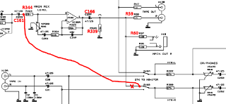
As in the UB502, the headphone amplifier gets
its signal via the "2TK TO CTRL ROOM" switch, which is
SW6A/SW6B in the schematic and on the board. I wanted to isolate
it from the signal coming from the main fader, then connect it to
the signal line going into into the main fader, as shown for the
right channel in this excerpt
from the schematic. Starting from an easily identifiable component such
as the RCA jacks, and using a multimeter to find zero-resistance paths
from component to component, I was able to identify the necessary
components on the board. Their reference designators on the circuit board
are marked here in red.
|

|
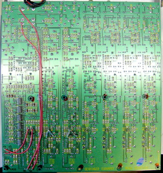
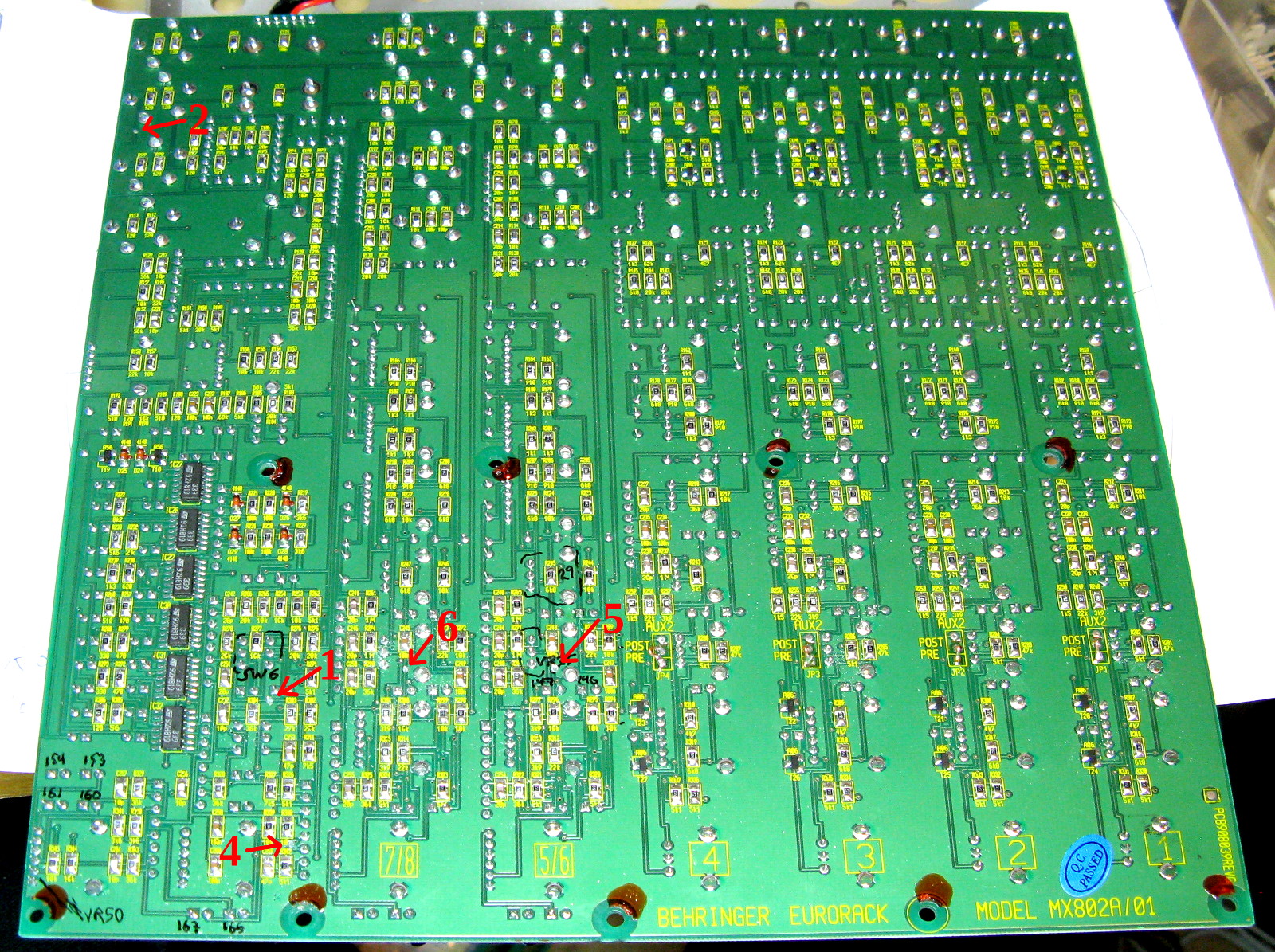
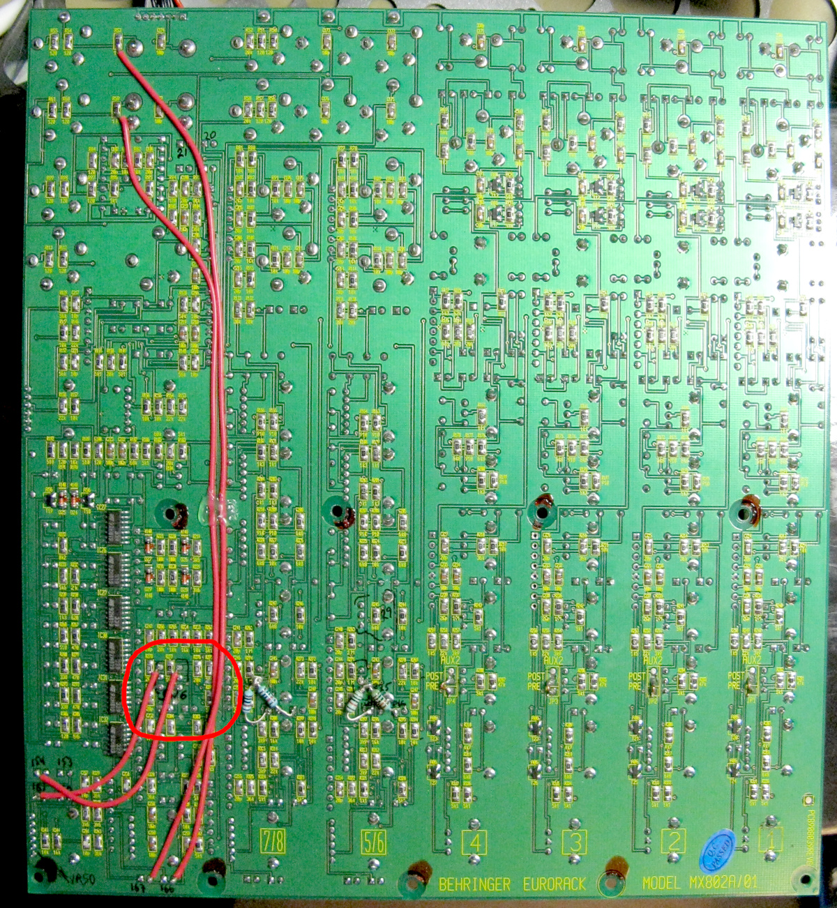
Click for a bigger picture of
the board's back side. I've labeled the places where I cut traces.
Note that cuts "5" and "6" are
unrelated to this headphone modification! Cut
"3" is missing from the picture, as that's on the
front side of the board. The
black markings on the board are my own scribblings from while I was trying
to decipher its components.
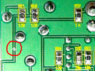
The switch terminals to isolate on SW6 are the ones furthest away
from the board's bottom edge. To isolate the left-hand one (which is the
right channel) I cut the trace leading downwards from it at a suitable
place where there's room to work with a Dremel tool's milling bit
(the cut labeled "1" in
the photo, click for a closeup)
and then verified with the multimeter that R339 and C166
(R345 and C259 in the schematic) had been isolated from the switch.
However, R59 and R60 (R20 and R37 in the schematic) were
still connected, so I had to make another cut (labeled "2",
click for a closeup) to isolate
those. Now the switch terminal is isolated
from all of them, however R339 and C166 are now also isolated
from R59 and R60, which is not the intention. So I will
have to wire those together again later.
|

|
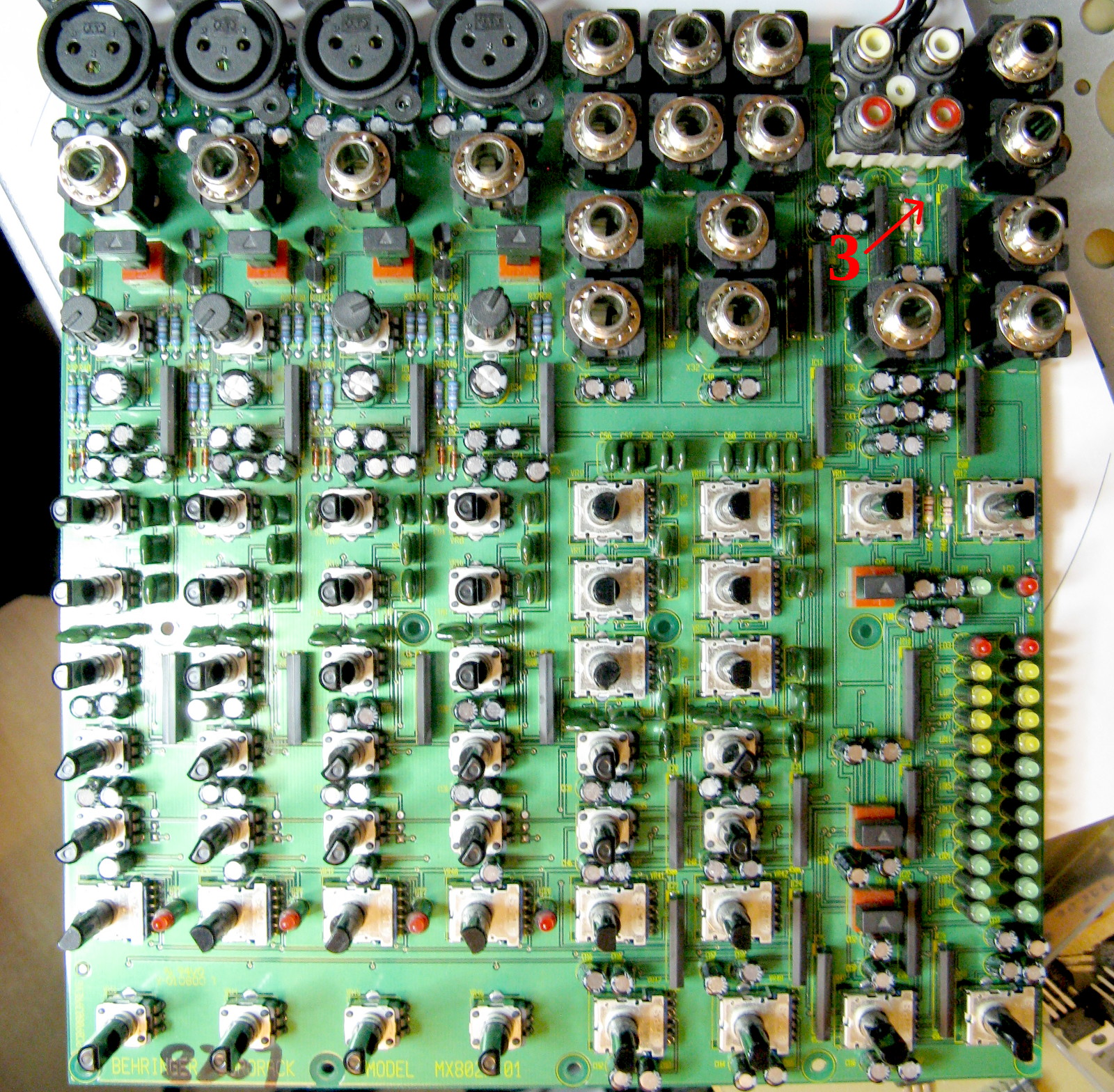
Click for a bigger picture of
the front side.
The traces going to the right-hand switch terminal (left channel) are a
bit more difficult to follow. One cut was more convenient to make on the
component side of the board, which I had already removed in order to
read the capacitor reference designators—I just had to make double
certain that I follow the trace correctly from one side of the board to
the other. (I could also have ground out the via right next to R53
on the back side.) I finally ended up cutting at a position marked
"3" on the front side
(click for a closeup), and at a position
marked "4" on the
back side (click for a
closeup).
As before, this also isolated C167 and R338 (C258 and R344
in the schematic) from R53 and R54 (R19 and R18 in the
schematic), so those too will have to be reconnected together again.
|
|
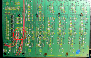
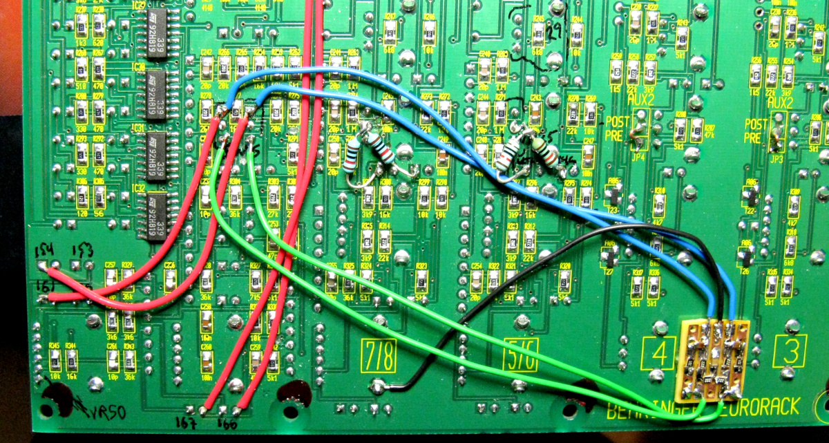
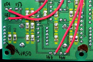
Click for a bigger picture of the
wiring. It is all on the back side of the board.
To reconnect the circuits which I had unintentionally cut in half in
order to to isolate the switch terminals, I soldered jumper wires from
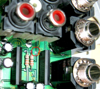
the lower end of R59 to the positive end of C166, and from
the lower end of R53 to positive end of C167 (see a
closeup of the capacitors,
at the bottom edge of the board, C166 is on the right, C167 on the left).
The two resistors are SMD versions, but entirely possible to solder to
regardless. I put a blob of hot glue at the midpoint in the wires, just
to help keep them in place. At this point, the modifications I've done
have isolated the two switch terminals, and nothing else.
I decided to take the pre-fader signal from the negative ends of
C161 (right channel, labeled C253 in the schematic) and
C154 (left channel, labeled C251 in the schematic, see a
closeup of the capacitors,
at the left-hand edge of the board, C161 is the lower one, C154 the
upper).
I soldered jumper wires from them to the now isolated left-hand terminal
and right-hand terminal of the switch, respectively. These are trivial to
solder, as they are all through-hole components. This completes the
modification.
|
The AUX send modification
The Behringer Eurorack MX802A has two AUX sends for each input channel.
AUX1 is pre-fader, AUX2 is post-fader. I wanted both AUX sends to be
pre-fader. I explain why on my
t.Mix MIX 802 page—that mixer
had just a single post-fader AUX send, which I wanted to convert to
pre-fader.
The MX802A has provisions to convert AUX2 also to pre-fader on the four
mono mic channels (the modification is explained in the user manual on
page 11). However, the AUX2 sends on the two stereo channels
do not have this provision, and I wanted to convert them to
pre-fader as well! Here's how I did that.
|
|
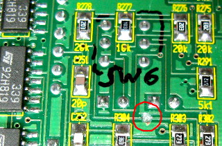
To isolate the AUX2 send of stereo channel 5/6, I cut the trace
leading from VR35 towards R295 and R296 (labeled
R283 and R309 in the schematic). The cut
is labeled "5" on the photo (click for a
bigger picture or
a closeup of the cut). This was
very obvious and easy. Likewise, to isolate the AUX2 send of stereo
channel 7/8, I cut the exact same trace leading from VR36
(labeled "6").
Note that cuts "1" through "4" are
unrelated to this AUX modification!
Both stereo channels occupy their own
strip of circuit board, and those strips have exactly the same
architecture and layout (likewise for all the mono channels as well),
so any channel-specific modification is easily replicated to other,
identical channels.
|
|
|
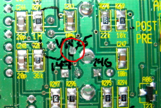
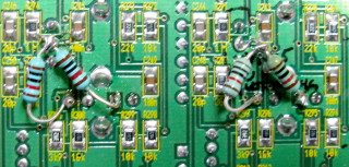
To reconnect the AUX2 send for stereo channel 5/6, I soldered
two 10 kΩ resistors to the middle leg of VR35. I
soldered their free ends to the negative terminals of C146
and C147 (labeled C220 and C221 in the schematic), which are
where the corresponding resistors leading to AUX1 are connected as well.
For stereo channel 7/8, I soldered two 10 kΩ resistors in
the corresponding positions, from the middle leg of VR36 to the
negative terminals of C148 and C149 (C222 and C223 in the
schematic, click for a
bigger picture or a
;closeup
of the resistors.) Note that the wires you see are unrelated to this AUX
modification!
|
Adding a "Natural Crossfeed Mixer" to the headphone
output
I had already installed a "Natural Crossfeed Mixer" circuit into
my t.Mix MIX802 mixer. The circuit is an ingenious
design by Jan Meier, which simulates a speaker "soundstage"
in headphones, making listening much more pleasant for the brain. The
crossfeed can be switched in and out of the circuit with the (otherwise
useless) "Tape to Phones" or "2TK to Ctrl Room"
switch. Read more about the circuit and that modification
here. I liked it so much that I decided
to install a similar circuit also into my Behringer MX802A.
I will show here the modification only, see the
original MIX802 modification for further
details, including circuit diagram and layout.
|
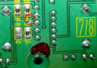
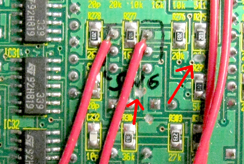
First I needed to isolate switch SW6 (the "2TK to Ctrl Room"
switch) from the 2-track (tape) input. This does not require removal
of the PCB. You just need to make two cuts in the immediate vicinity of
SW6, circled in red in this
photo. The red wires and the leaded resistors are from earlier
modifications, i.e. the headphone volume
modification and the AUX modification. This
crossfeed modification can be done with or without those modifications.
See this closeup for the
exact locations of the cuts. One is in the wire coming from the lower-left
terminal of SW6, the other is in the wire coming downwards from
the 20 kΩ R275 (labeled R280 in the schematic). The
third cut you see in the photo is unrelated to this modification.
|
|
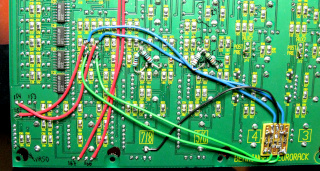
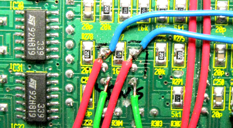
As before, I built the Meier circuit on a tiny piece of veroboard, which
I hot glued onto the PCB at a suitable free spot, and then
attached its wires to SW6. The input wires (blue) attach to the
upper two terminals (the ones towards all the connectors on the PCB) and
the output wires (green) to the corresponding lower two terminals. See
this closeup of the
switch terminals. The black wire is connected to ground wherever is
convenient—I used a chassis pin of one of the potentiometers.
If the headphone volume modification has been done,
there will already be wires coming to the upper terminals—the new
wires are simply added there as well. This modification can also be done
without the headphone volume modification.
|
This was quick and easy to do, and now the headphone output can either
carry the original stereo signal as-is (with the "2TK to Ctrl Room"
switch in the up-position), or through the Meier circuit (with the switch
in the down-position). In case I ever want the crossfeed-mixed signal to
an external amplifier for any reason, the same signal is available at
the "Ctrl R Output". The "Main Out" is, of course,
unaffected. Together with the headphone volume modification,
this mixer has the best of all worlds for both headphone listening and for
controlling speakers!
Bad power supply capacitors
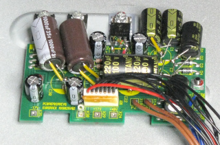
Oh, by the way, before you reassemble your mixer, take a look at the
capacitors on the power supply board (the small PCB attached to the bottom
of the case). See any brown gunk oozing from
underneath the plastic shell near their tops like I did? Or are they
actually swollen, like they were in my
Behringer UB502? Geez, how cheap electrolytics
does Behringer use in their power supplies??? While you have the thing
open, consider replacing them as well, to avoid another service a year or
two later!
|
However, there's very little extra room inside the mixer,
so the replacement caps must not be any taller then the originals
(which are 21 mm tall). I actually could not find suitable ones
anywhere, which is why I had to place them so helter-skelter. (I
also couldn't immediately source any 100 μF 100 V caps,
so I substituted 2×47 μF in parallel.)
Come to think of it, might this explain why the caps fail in the first
place? Some poor sap designed the mixer's chassis too small, forcing
Behringer to use some sub-spec capacitors because they're the only ones that
will fit? I mean, caps fail in SMPSs every other day, but to fail in a
linear power supply, they really have to be bad!
|
If you do choose to replace them (yes, it will be a pain in this case),
use good-quality 105°C ones of the
same capacitance and same or higher voltage rating. I generally use
low-ESR for pretty much everything—they're not ridiculously expensive,
so I see no reason to keep "ordinary" ones in shelf, although
they'd be just fine in this case. Generally low-ESR ones may be slightly
bigger then ordinary ones, but I just couldn't find physically small
enough caps of any type!
A word of caution
There's nothing especially difficult about these modifications, but if you
do manage to break something regardless, you now have a broken mixer,
congratulations! So don't attempt this modification unless you
know what you are doing and are willing to take that risk, and in any case
don't blame me for anything bad that happens! (You did read the
bit in the beginning, about component reference designators I found on the
circuit board not matching those I found on the schematic, right?
Right?)
Antti J. Niskanen <uuki@iki.fi>

