<HOME
<Electronics

An overkill passive PoE injector for Raspberry Pies

tl;dr? Here's the schematic. Really it's just a glorified splitter cable in a box with some LEDs. And it looks like this. The remote ends use splitters like these (the one with the DC plug; although these come in pairs, I don't use the one with the DC jack). I use them like this and like this.

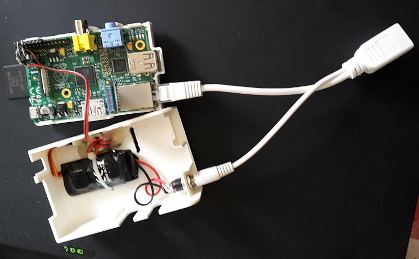
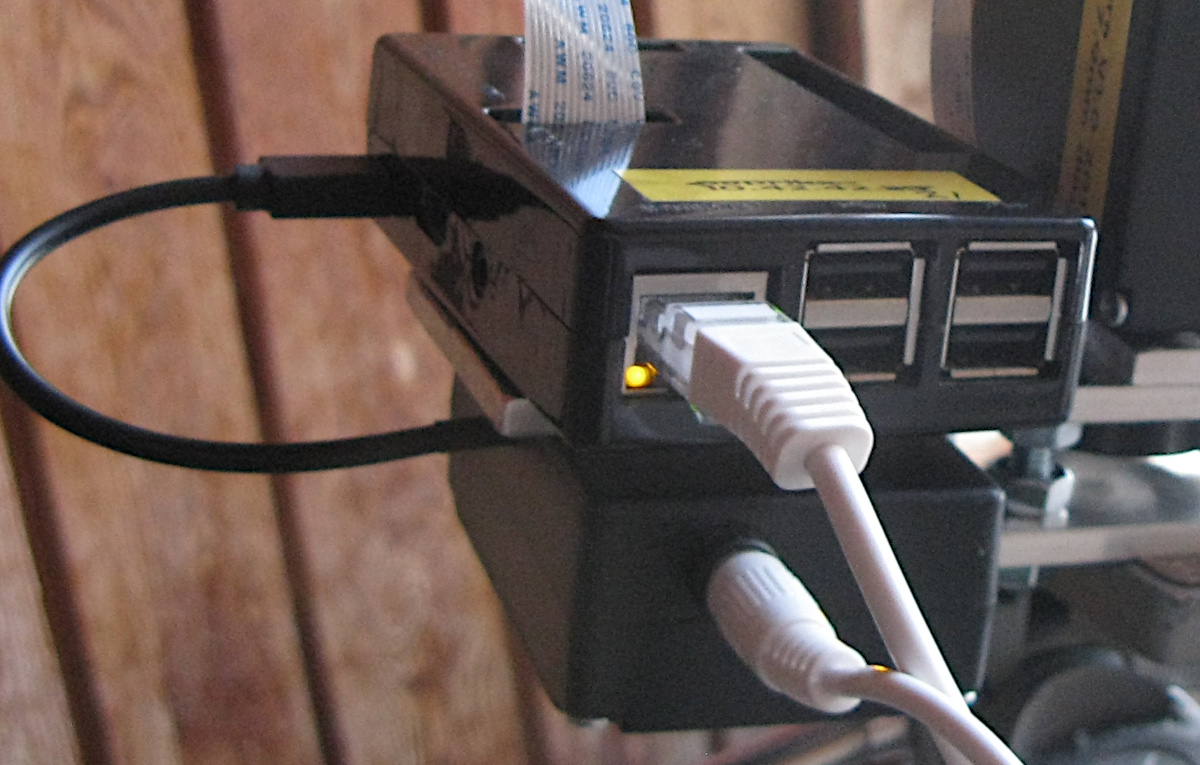
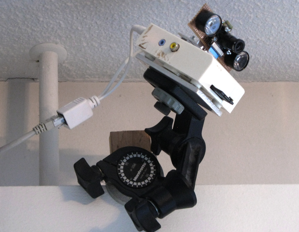
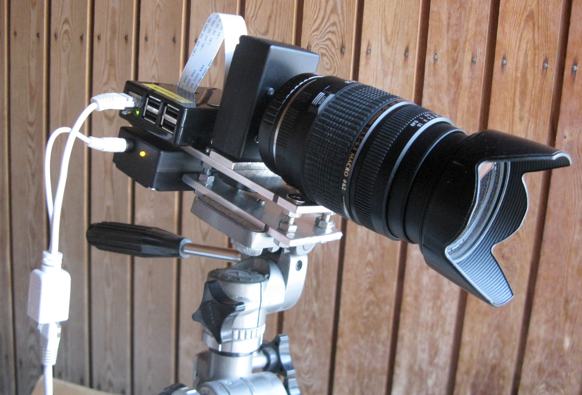
We all have a bunch of old Raspberry Pies lying about, right? I certainly do. I've dedicated a couple of them for use with cameras—one old "NoIR" camera with IR lighting, and the new and fancy "HQ" camera. I use them for time-lapse things, one e.g. for watching how I sleep at night, another for watching icicles grow. For convenience of placement, I've fitted them both with passive Power-over-Ethernet (PoE), so I only need to hook up a single Ethernet cable and not worry about the power supply. Now, the newer Pies can be fitted with actual "real" PoE (IEEE 802.3af or 802.3at), but those "hats" on the Pi end cost money, and they also require "real" PoE injectors at the other end, which also cost money. Also, at least the official "PoE+ hat" for the Pi 3B+ or the Pi 4 runs quite warm, and has a noisy fan running even when the Pi itself is idle!

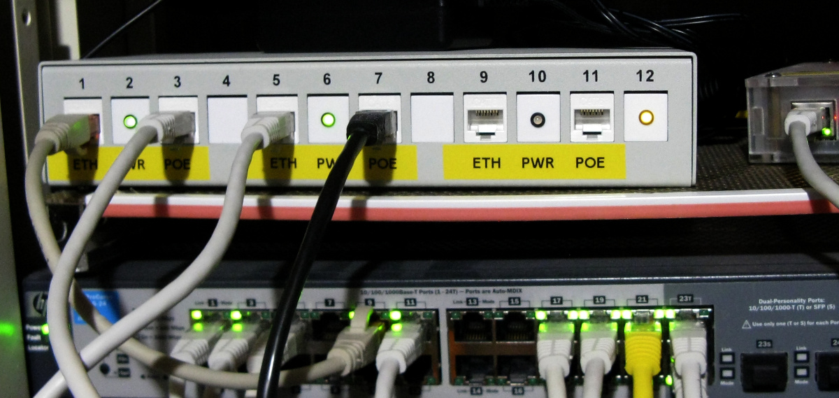
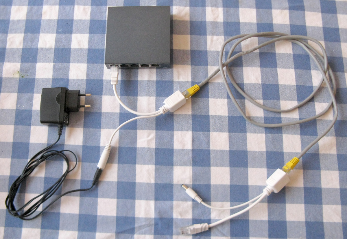
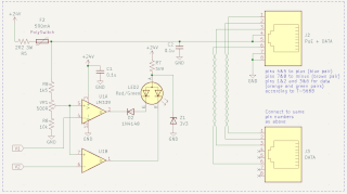
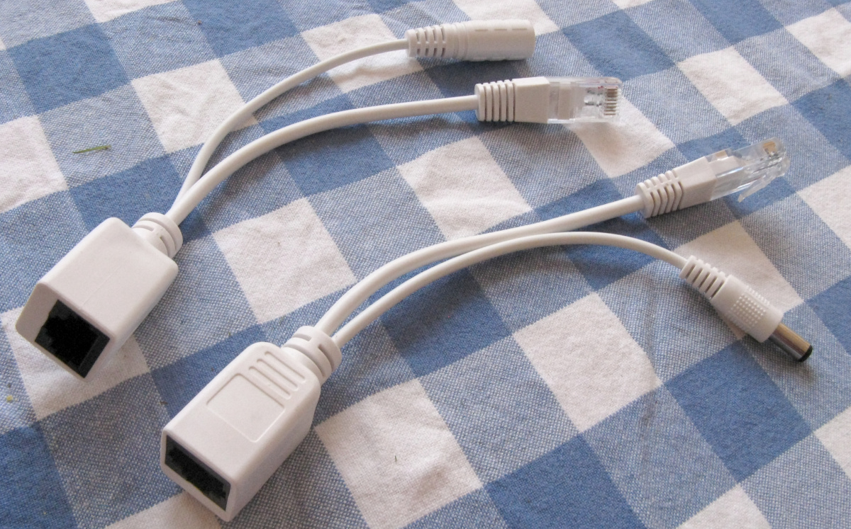
So I went the passive PoE route, and built a totally overkill three-channel injector device to use with a bunch of cheap passive splitter adapters from eBay.

Unlike "real" PoE, the "passive PoE" costs next to nothing. Since 10baseT and 100baseTx (10M and 100M) Ethernet only use two of the four pairs of wires in a standard Ethernet cable, the other two pairs can be used as power leads. Passive PoE adapters (see a closeup here) are available on eBay and elsewhere, and come in pairs where one has a DC jack, the other a DC plug. If you have a device that gets its power via a DC plug and interfaces via 10M/100M Ethernet, these adapters can be used to deliver them both over a single cable, as demonstrated here.

Of course, 1000baseT gigabit Ethernet cannot do this, since it needs all four pairs for data, but the older Pies don't even have GbE, and even with the newer ones (3B+ and later), you don't really need it for simple, low-throughput applications like a still camera, weather sensors or home automation.

Another limitation is caused by the resistance of the (possibly quite lengthy) Ethernet cabling, and all the connectors along the way. Anything drawing significant current from, say, a 5 V power supply may end up with a serious undervoltage problem and not work at all! But anything that works on, say, 19 V, is sure to have a switch-mode power supply producing the 3.3 V or 5 V it actually operates on. That will work just fine even if the input voltage were only, say, 17 V due to excessive voltage drops. And since higher voltage to the SMPS means lower current draw, the voltage drops won't even be as bad. Which is why, for this passive PoE system, I'm using a 24 V feed and a dedicated 5 V step-down converter for each Pi.

Passive PoE for Pies

Here is a Raspberry Pi 1B, which gets its power through a Turnigy branded RC "UBEC"—a Universal Battery Eliminator Circuit—used in radio controlled toy planes, cars etc. to provide 5 V for the radios, servos and other stuff, from the typically much higher battery voltage that the motors run on. During testing, I had one melt down when providing its "continuous" rated 4 A (what did I expect from a cheap Chinese hobby-grade component?) but I've run a Raspberry Pi for ages on one, drawing the few hundred mA that it does. The UBEC fits inside the Pi's case (held in place inside the lid by a plastic zip tie), and the original Pi 1B, with only two USB ports on it, has a free spot on the case for a DC connector to bring in the 24 V. The 5 V output from the UBEC is fed to the Pi via its GPIO header, which is an accepted way of providing power, no matter what anyone says. I did add a 1 A fuse just for safety's sake (the micro-USB power connector supposedly has some kind of PolySwitch or similar overcurrent device on it).

When the case is closed, the passive PoE splitter plugs into the Ethernet port and DC jack so neatly that it looks like the Pi was designed this way from the beginning! Mounted on the top of the case is an early "NoIR" camera module and IR LEDs.

Here is a Raspberry Pi 3B, similarly powered over passive PoE (and also sporting a camera, of the "HQ" sort, with an adapter for Canon EF compatible lenses—just a bit fancier than the one on my 1B), only here the step-down converter is in an external box. The converter is a JoyIT SBC-Buck02 (hmm, I wonder where the "SBC" in the name comes from...?), rated at 5 A max (again a really healthy safety margin), whose two big electrolytics I replaced with known good low-ESR ones for good measure (actually I needed to mount the caps horizontally to make the thing fit in the box). Again, I have a 1 A fuse between the DC jack and the converter, and also an LED shining out from the side of the box. The 5 V output goes to a short micro-USB cable that sticks out the side, and connects to the Pi.

Not quite as nice as the above Pi 1B, but what can I do, since the later models have additional USB ports where I'd like the DC jack to be...

A multi-channel passive PoE injector

For the injector side, the passive adapters offered a ready solution, but that would have needed several power supplies, or at least a splitter adapter, to feed them. So I made a totally overboard splitter adapter. It is fed by a single 24 V 1.7 A power supply, and provides three outputs individually fused with automatically resetting 0.5 A "PolySwitch" PTC devices (and a 2 A main fuse... do you sense a streak of paranoia in my designs?). Easy enough, but I really wanted some indicator LEDs! What could I indicate on a multi-port passive PoE injector, if I don't monitor the actual Ethernet link for activity? Well, power consumption—i.e. whether or not the remote device is drawing power, i.e. whether or not the remote device is on!

So here is the final 3-channel passive PoE injector, with remote power sensing and corresponding indicator LEDs. I did away with the injector-side cable adapters, wiring up six keystone RJ45 modules instead, which I fitted in a run-of-the-mill keystone enclosure (a 12-module LogiLink NP0094 consolidation box). I also bought a bunch of blank caps that I drilled for adding LEDs. I could just as easily have made a 4-port injector, but I just don't see myself needing that many passive PoEs, and preferred instead to leave an empty space between each individual injector channel.

The "ETH" ports connect to my managed switch, and the "POE" ports, of course, go to the patch panel, which is wired to remote RJ45 sockets elsewhere. The indicators are two-color LEDs that light up green when the remote device is drawing any current (the threshold current is adjustable), or red if the overcurrent protection has tripped. When the LED is dark, it means the remote device is off, or disconnected.

Here is the schematic for the injector. It uses two sections of an ordinary LM339 quad comparator to detect the voltage drop over the resistor and PolySwitch, with an adjustable threshold for the green LED ("power on") and a separate, much higher threshold for the red LED ("overcurrent fault"). Note how the two LEDs will never both shine at once, since both are fed via the same anode resistor, and the green LED has a higher voltage drop, especially with its additional series diode—which might be unnecessary, but will make it absolutely certain. The Zener may also seem entirely unnecessary and redundant, but I found that the transition between the on and off states was kind of fuzzy, and the threshold voltage was imprecise, if the LM339's output(s) were subjected to the full 24 V voltage! Very strange (hmm, I should have checked with an oscilloscope to see if it was actually oscillating...), but easy to fix with the Zener. A single LM339 quad will provide for two channels, so for three or four channels, two ICs are needed. Since I only implemented three channels (and I'm already having second thoughts...) and thus used only two comparators from the second IC, I connected the two unused ones to well defined unequal voltages as is recommended for opamps as well.

I used multi-turn trimmers for setting the green LED's threshold, but that turned out overkill—a single-turn trimmer would do just fine, if the fixed resistors are chosen with reasonable care. Adjustment was simple: Connect a Pi to the output, wait until it's booted up and idle, then adjust the trimmer so the LED remains well and truly lit. Then power down the Pi, and confirm that the LED goes out. The LEDs worked with all my Pies from 1B to 3B at the same threshold settings. Pi 4B and up may be different, though—I hear at least the 4B may draw significant power even when shut down!

I don't know if there's any standard or common practice for the polarity of the power carrying wires in a passive PoE system—I just followed the same pin designations as the cheap splitter adapters I used at the remote end of the cable, obviously. You'd be well advised to check the output polarity with a multimeter before connecting anything! Also, beware of "crossed" Ethernet cables! If you want to use a passive PoE system with a gigabit interface, you'll need to configure it to limit itself to 100M—at least the Pi 4B does not do this automatically! Even with two pairs missing from the link, it would try and try and try to establish a 1000baseT connection, never succeeding. To force the link to 100baseTx, use the command

      ethtool -s eth0 speed 100

A word of caution

The 24 V voltage used here, or the 48 V used in many "real" PoE systems is not a great big electrocution risk to humans, but it can definitely damage things designed to work on 5 V, like the Raspberry Pi. It can also damage other equipment that is not intended to see such voltages on its Ethernet port. By playing around with DIY PoE, you do run a very real risk of damaging something by mistake! So don't mix up the "ETH" and "POE" ports, don't forget which cables are carrying power, verify your cables are correctly wired straight patch cables, and even so, check the polarity at the remote end with a multimeter before connecting anything! Don't attempt any of this unless you know what you are doing and are willing to risk damaging your stuff, and in any case don't blame me for anything bad that happens!


Antti J. Niskanen <uuki@iki.fi>