<HOME
<OH2GVB
<Electronics

OH2GVB Quadrifilar Helical Antennas

Simulation of QHAs   <>   Other QHAs I've built


The Quadrifilar Helical Antenna (QHA, or QFH if you prefer) has two defining properties: (1) Its radiation pattern is just about as perfectly hemispherical as you will ever find. (2) Its radiation is just about as perfectly circularly polarized as you will ever find, in all directions. This makes it ideal for a number of uses. Satellite reception (and transmission) may be number one among them. Many people use some form of QHA to receive weather satellite images, and have great success with it. In the ham community, satellite enthusiasts seem to prefer the Eggbeater instead, although its radiation, instead of remaining circularly polarized throughout, tends to become more and more horizontal at low elevation angles. Circular polarization is no prerequisite for working amateur satellites, as they mostly have linear antennas on them. However, you never know what orientation the satellite will be in, so you don't know how to orient your linearly polarized antenna. A circularly polarized antenna will give a consistent signal regardless of the orientation, at a cost of 3 dB in signal strength, compared to a properly oriented linear antenna. However, when the linear antenna is in the worst orientation, the resulting null may be very, very deep indeed.

An antenna for VHF and UHF

I had used my FT-897 exclusively on HF, and only found myself on VHF and UHF after buying my Wouxun handheld. Thereafter I finally began considering what kind of VHF/UHF station antennas I should build for my QTH.

After looking at various dualband antennas like the VHF/UHF groundplane antenna presented in the ARRL Handbook, and the ubiquitous J-poles with their various improvements for dualband operation, I got to thinking about satellites. There's still an easy FM bird or two up there, and of course the ISS. Since the local VHF and UHF repeaters are very strong at my QTH, any antenna at all would do for accessing them. So I might just as well optimize my antennas for sky coverage, and try my luck with the sats—I'd still be able to work the repeaters just fine.

Eggbeater or QHA?

Eggbeater antennas are very popular for amateur satellite use, and have the additional advantage of being able to switch between right-hand and left-hand circular polarization (RHCP and LHCP). But having used QHAs for various uses such as GPS reception and telemetry transmission from an amateur rocket, I was already familiar with them and their radiation patterns and polarization characteristics. Also, the QHA's polarization remains circular down to the horizon, whereas the Eggbeater becomes horizontally polarized—not so hot for the vertically polarized terrestrial repeaters!

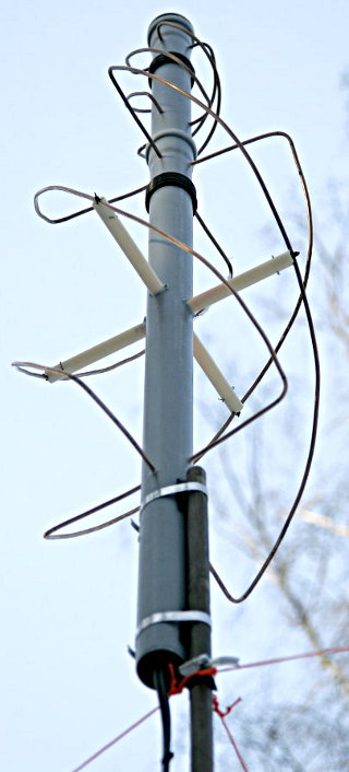
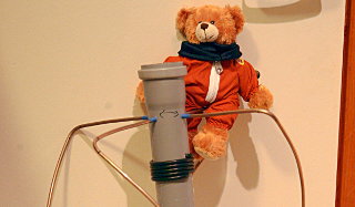
Also, QHAs look totally cool.

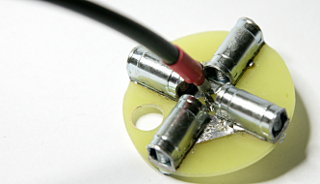
Thus I chose to build a pair of QHAs, one for 2 m and one for 70 cm. A diplexer is of course needed to connect both to the single antenna connector of a dualband radio, but these are relatively cheap (and I suppose quite easy to make as well). I finally went for a triplexer (a Diamond MX-3000N) which also includes the 23 cm band, just in case. For the time being, the 23 cm port is populated by a 50-ohm termination.

RHCP or LHCP?

This is where an Eggbeater scores over a QHA—a relay-switchable phasing line can be used to switch polarization between RHCP and LHCP. With the QHA, I had to choose one. I arbitrarily chose RHCP, since that's what weather satellites use (who knows, I might try receiving those some day, as 137 MHz isn't that far from the 2 m amateur band). Amateur satellites mostly use linear polarization, so choice between RHCP and LHCP isn't critical.

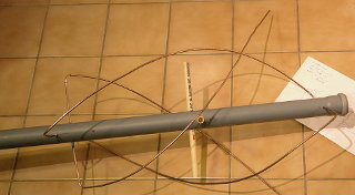
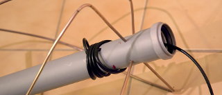
Since the structure of the QHA is quite hollow, I would very much have liked to build the smaller 70 cm antenna inside the larger 2 m one. I did a lot of simulations on this, and finally decided it wasn't worth the trouble. I built them separately, and mounted them on top of each other. Below are some notes on the construction of these antennas, and here I've outlined what I learned from the simulations. There's also a program I've used to make NEC2 models of QHAs.

Construction of the QHA

Connection points for the helices

The QHA is composed of two wire loops, one slightly larger than the other, twisted into helices. The feedpoint is at the top, where the feedline connects to both loops. One loop is slightly above resonance, the other just below. Thus one loop is slightly inductive, the other one slightly capacitive. This causes a phase difference between the two, leading to circular polarization being radiated. When fed in parallel, the opposite reactances cancel each other, and the whole antenna appears 50 ohm resistive.

I used 3/16" copper-nickel brake tubing to make the helices. According to John Coppens's Quadrifilar online calculator, this tubing diameter is ideal for the 70 cm version, but too thin for 2 m. What "ideal" means here is still a mystery. This tubing was nice and easy to work with, and easily available, which is more important. To connect the feedline, I made small printed circuit board connection plates (one per antenna) to which I soldered the coax, and attached the helices with screw terminals.

The screw terminals came from 30-amp break-off screw terminal blocks. These are known as "sugar cubes" (sokeripala) in Finnish, I've seen them referred to as "choco blocks" also. I cut away the plastic insulation, tinned the flat surface of each terminal, fabricated and pre-tinned circuit boards, and soldered everything together. I had to grind down the terminals a bit in order for the whole thing to fit inside the 50 mm sewer pipe I was going to use as the body of the antenna.

The sewer pipe body and brake tube elements

After drilling the sewer pipe and measuring and marking the brake tubes, I pushed the tube through the sewer pipe and began bending. I made the 90-degree turns with the help of a small length of iron tube of suitable diameter. Then I formed the helices freehand.

Helices and supports

I stuck the ends of the helix into the holes drilled in the sewer pipe to temporarily hold them in place. I then continued to work on the helices until they looked somewhat alright.

Since the tubing is quite thin and easily bent, I made extra supports for the 2 m version. They go through the sewer pipe, and are kept in place by split pins. Grooves are made in their ends for the tubing, which is attached with an arrangement of split pins and cable ties.

Coax feedline

Before attaching the feedpoint, I threaded the coax feedline through holes in the sewer pipe, and wrapped it around the pipe five times. This will become the choke balun for the unbalanced feedline. I left a good length of coax hanging out of the top end of the sewer pipe, and I kept the turns around the pipe loose for the time being.

Feedpoint attachment

Now the coax feedline was soldered to the feedpoint PCB. A cable tie was tightened onto the coax some way down from the feedpoint. This is to relieve stress, so the coax isn't torn off the PCB when I tighten up the windings of the balun. I applied some RF-conductive anti-corrosive goop (Butternut "Butter it's not") on the insides of the terminals.

Next the whole PCB was fitted inside the sewer pipe, the helix ends were pushed into the screw terminals, and the screws were tightened via the top end of the pipe. Which helix connects to which terminal is crucial! Getting this wrong will point all radiation into the ground, rather than skyward. Click the image on the right to see how the loops should be connected for skyward-pointing right-hand circular polarization (and yes, the helices in a right-hand polarized QHA are supposed to be left-hand spirals!). The image depicts the connection plate PCB, the black patterns are the copper foils. The coax center and braid can be connected to the foils either way, it does not matter. Here I explain how the direction of the helices and the configuration of the feedpoint affect the radiation direction and polarization.

Coax choke balun

Finally, the coax was pulled out so the cable tie was against the inside of the sewer pipe, the choke balun coils were formed tight against each other, and the coax slack was pushed through into the tube and out the bottom. Except for the connector at the end of the feedline, the 2 m QHA is now finished.

Remember RF safety! The bear was removed to a respectful distance before testing this antenna.

70 cm version

The 70 m QHA is identical to the 2 m one, except no extra supports for the helices are needed. The top end of this sewer pipe is closed off with an end cap. The bottom end fits into the top of the 2 m QHA's pipe.

Before soldering the connector onto this feedline, remember to thread it through the 2 m QHA's pipe! (This is what the extra hole in the screw terminal PCB is for, by the way.)

How it works

I calculated the measurements for both QHAs using John Coppens's
Quadrifilar online calculator. The SWR minimum of the 2 m QHA was close enough according to my antenna analyzer, and the impedance was quite close to 50 ohms. My analyzer of the time didn't go to UHF, but the radio was happy enough with the antenna.

What was a surprise to me, was how well the 2 m QHA was matched also at 70 cm. Yes, we all know it's a harmonic and therefore is supposed to work, but the NEC2 simulations I had done earlier suggested otherwise! Oh well. Anyway, I don't know whether the radiation pattern and polarization characteristics are as good with the 2 m antenna on 70 cm, so maybe it's just as well that I built also the 70 cm one.

The local repeaters come in strong with the QHAs, as I expected. Next I'll go ahead and try how well the satellites work.

These were not the first QHAs I built. My first experience with QHAs came from a GPS antenna that went onboard an amateur rocket. I wanted circular polarization and an omnidirectional radiation pattern, so I chose a QHA. I often had the same criteria for other airborne antennas, so I have built several different QHAs over the years.

Details on the simulations I did, as well as the model generation software helix2nec, are on a separate page.


Antti J. Niskanen <uuki@iki.fi>