<HOME
<OH2GVB
<Electronics
Simulation of Quadrifilar Helical Antennas
OH2GVB QHAs <>
Other QHAs I've built
helix2nec: The model generation software
I simulated a bunch of QHAs and dual QHA combinations using the NEC2
simulation software. To aid in generating the NEC2 models, I wrote a
simple and stupid (and incredibly ugly) program in C to automatically
generate NEC2 source code according to given QHA dimensions (height,
diameter, number of twists and so on). It can generate either a single
QHA or multiple QHAs stacked according to your preference. It does not
generate QHA dimensions for your design frequency—for that you'll want
to use John
Coppens's Quadrifilar
online calculator. Take the dimensions it gives, and plug them
into helix2nec.
If you like, you can download helix2nec.c.
It's not pretty. You can also download an example input file,
dual_435.helix, which creates a NEC2
model of the 2 m and 70 cm combination, and tells NEC2 to
simulate it in the UHF range.
The input file's structure is as follows:
- The first line defines how many helices there will be.
- The following lines define each helix, one helix per line. There must
be as many lines as the first line specified. Each line contains, in
this order:
- Height of the larger loop
- Diameter of the larger loop
- Height of the smaller loop
- Diameter of the smaller loop
- Bend radius (of the 90-degree turns)
- Wire diameter
- Number of twists in the helix
- Vertical offset of this helix
- Angle offset of this helix (in degrees)
- Feed type: F=feed, T=terminated, O=open, S=shorted
All lengths are in millimeters, measured from the center of the conductors.
The model must contain precisely one helix with feed type F, other
helices must be terminated, open or shorted.
- The last line specifies the start frequency, end frequency, and
frequency increment, in MHz.
This will produce a right-hand helix with anti-standard
feedpoint configuration. (Mega-oops, until January 2024 I had a mistake
on this page, claiming this would create a model of a left-hand helix
with standard feedpoint. So sorry for any
confusion!) When the feedpoint is located at the top, the antenna will
radiate skyward with left-hand (LHCP)
circular polarization. (And until January 2024 I had this wrong also,
claiming it was skyward and RHCP—which it would have been
with a left-hand helix and standard feedpoint.) See
below for how to choose the twist direction and
feedpoint configuration, if you want other polarization or radiation
direction. If you want to model a QHA with left-hand twists, specify
a negative number for the number of twists in the input file. To get an
anti-standard feedpoint, exchange
the dimensions of the larger loop and the smaller loop with each other.
There is no simple way to move the feedpoint to the bottom, so if that's
what you need, just stand on your head when you view the results.
Compiling the program:
gcc -ohelix2nec helix2nec.c -lm
Using the program:
   helix2nec blah.helix blah.nec
   xnecview blah.nec
   nec2c -iblah.nec -oblah.out
   xnecview blah.out
Do not complain about what the program does, or doesn't do. I do not
support it in any way.
Helix and feedpoint vs. radiation and polarization
With very minor changes, the QHA can be tailored to radiate upwards or
downwards, with RHCP or LHCP polarization. The two factors that determine
the antenna's properties are (1) the direction of the helices
(i.e. the direction of the "twist" of the antenna) and
(2) the connection of the feedpoint. Do not assume that
left-handed twists automatically mean left-handed polarization! It is,
in fact, the exact opposite!

|
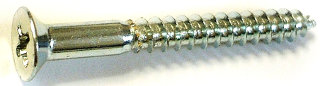
Direction of the helices: This is rather simple. The picture on the
left shows one QHA with left-hand twists. They are in the opposite direction
as the threads on a screw. A QHA with twists going in the same direction
as a screw, as shown in the images on the right, has right-hand twists.
|
|
|
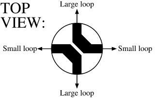
Connection of the feedpoint: This is a bit more subtle. When the
antenna feedpoint is at the top of the antenna (which for some
reason seems to be the commonly used arrangement, perhaps because it
enables making sleeve baluns for the feed; something I've never done
myself) the two loops can be connected according to the diagrams on the
left or right. Note that the diagrams are looking downwards on the antenna
feedpoint from above; as labeled on the diagrams, they are
top views. The coaxial feedline is connected to the two thick black
areas (they represent conductors on circuit board, which I used to make
the connections in these antennas).
It does not matter which one is the center conductor and which one
the coax shield.
If you follow the diagram on the left, you will get what I shall
hereby call the "Standard connection" (just because this
is how I connected the QHAs at my station).
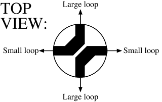
Now be extra careful, because this change is subtle and has major
consequences. Still
keeping the feedpoint at the top of the antenna, and still viewing
the feedpoint from the top, if you exchange the two loops, in
other words if you connect the smaller loop where it
says "Large loop" and the larger loop where it says
"Small loop", you will get what I shall call the
"Anti-standard connection". This is actually the
mirror image of the standard connection, and is shown in the
diagram on the right. (Rotate this diagram 90 degrees clockwise or
counter-clockwise, and you'll see what I mean about exchanging the loops.)
|
|
The effects: Again, when the antenna feedpoint is at the top of
the antenna, this is how the direction of the helices and feedpoint
connection affect the antenna's properties:
| Helices: |
Feedpoint: |
Radiation: |
Polarization: |
| Left-hand |
Standard |
Upward |
RHCP |
| Right-hand |
Anti-standard |
Upward |
LHCP |
| Left-hand |
Anti-standard |
Downward |
RHCP |
| Right-hand |
Standard |
Downward |
LHCP |
The first row represents my station's QHA antennas: skyward radiation with
right-hand circular polarization. The second row, where both the twist
direction and the feedpoint have been mirrored, is a complete
mirror image of the entire antenna. It is therefore logical that it
should otherwise work the same as the original, but have opposite
(left-hand) polarization.
The third and fourth row describe antennas that differ from the first one
in only one parameter (twist or feedpoint). They provide either RHCP
or LHCP polarization, but they radiate downward, into the ground. That
might seem useless—unless the antenna is hung from its
feedpoint (feedline going up), and
used to transmit telemetry from a high-altitude balloon! Alternatively,
you can mount the entire antenna upside-down, i.e. with the feedpoint
at the bottom, and get skyward radiation. Try this, if you think a
bottom-fed antenna would be more convenient for your application.
If you build a QHA for satellite use and find that it does not work, please
check, double check and triple check the twist direction and
especially the feedpoint
connection, and their resulting radiation direction with respect to the
location of the feedpoint. It is all too easy to design a QHA for sky
coverage, but build one that radiates down into the ground. (It's also too
easy to mis-interpret xnecview wire diagrams, which is why I had made a
booboo and had wrong information regarding the above antenna simulation
thing until January 2024. The above table and the Standard and Anti-Standard
connection diagrams were correct, though. I hope.)
Various double QHA designs
Here are some designs I simulated before building my pair of QHAs. Since the
QHA structure is "hollow", I was most interested in the possibility
of placing the small 70 cm QHA inside the larger 2 m QHA,
and wanted to
see if any unwelcome interaction would result between the two antennas.
Note that these models and simulation results are for LHCP antennas,
whereas I finally chose to build RHCP ones! The RHCP versions are
just mirror images of these antennas
(see above
how the helix direction and feedpoint connection affect the radiation
pattern and polarization), and the simulation results are equally valid
for either case.
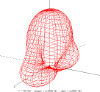
(Click on the images to see bigger ones!)
|
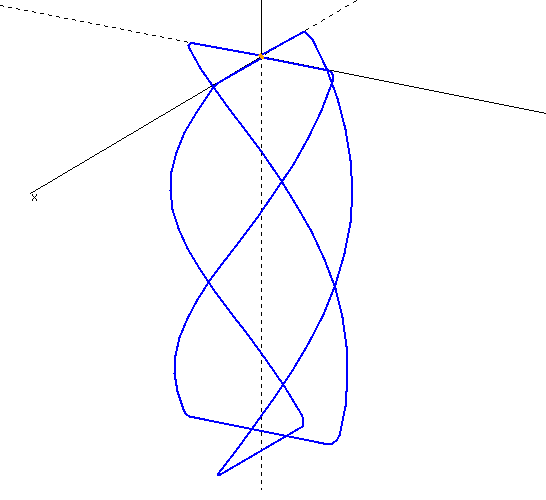
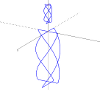
This is a NEC2 model of a single QHA. The feedpoint is at the top.
|
|
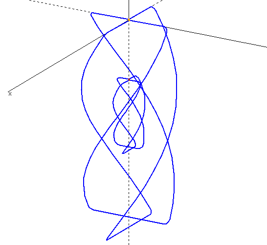
This picture shows what I wanted to make. The two QHAs are completely
independent,
but the 70 cm QHA is built inside the 2 m QHA. Since the 2 m
antenna is resonant also on 70 cm, I was worried the outer antenna
might shield the inner one, or at least change its impedance drastically.
Therefore I created NEC2 models of a single 2 m QHA, a single 70 cm
QHA, and various combinations of the two. Some main results are presented
below.
|
|
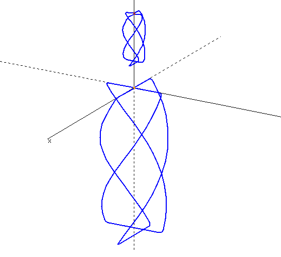
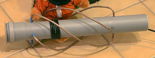
This is what I eventually built. As it turns out, the two helices can be
placed as close together as you like, without much interaction. With just
10 cm space between them, the radiation patterns of both are essentially
unchanged. The final reason why I chose this design instead of the one above,
was ease of construction, plain and simple. I still think the above design
would have been more elegant, though.
|
Some simulation results
Only one QHA will be fed at a time, so in the dual helix models, I had only
a single feedpoint, feeding the antenna whose performance I was interested
in. The other antenna was either terminated in 50 ohms, left open, or
shorted, to mimic what would happen when it's connected to a diplexer or
an antenna relay. Apparently this had very little effect on anything. I
terminated the antenna in the following simulations. (I did not try what
would happen if the two antennas were fed in parallel.)
I started by simulating a single QHA. Once I had all the bugs sorted out in
my code, the simulation results were in good agreement with Coppens's design
tool. The resonant frequency was just a tad off, and SWR was not exactly
1.0, but this could just as well be a non-ideality of the NEC2 simulation.
So rather than focus on the SWR curves produced by any one simulation, I
compared the results of single helices to those of dual helix arrangements.
|
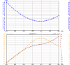
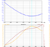
On 2 meters, the SWR curve of the dual helix arrangement was
practically identical to a single 2 m QHA. This is to be expected, as
the UHF QHA has no resonance on 2 m. However, the VHF QHA does do
something funny on 70 cm, which is its third harmonic.
It looks like it's not a good
enough resonance to be useful (though when testing the completed antenna
I noticed it performs just fine also on 70 cm),
but I was afraid it would mess up the 70 cm
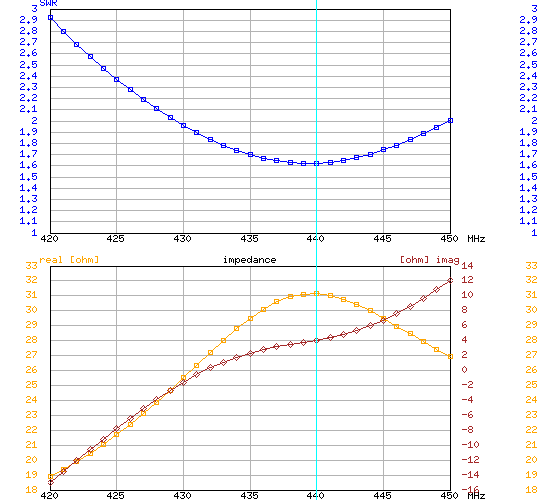
antenna's performance. But as it turns out, the SWR curve of the
dual QHA combo at 70 cm (right-hand image) remains nearly
identical to
a single 70 cm QHA (left-hand image). The minimum SWR
frequency does move a few MHz, from 440 to 442 MHz.
|
So far so good: the SWR of either antenna remains unaffected by the presence
of the other, and even the resonance frequency is unchanged. Also the
radiation pattern of the 2 m antenna stays clean, but what does
change is the radiation pattern of the 70 cm antenna.
|
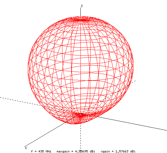
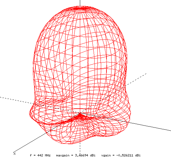
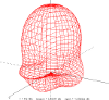
Shown here are the 70 cm radiation patterns of a single helix
(left), the
dual helix combo at its resonance frequency (middle) and the dual
helix at its design frequency (right). As can be seen, the radiation
pattern seems to change quite dramatically, but the biggest effects are
close to the horizon. Overall, the helix still radiates primarily into the
upper hemisphere without any major lobes or nulls.
|
So in conclusion,
the changes in the radiation pattern aren't really that bad. The
polarization does not change by much either. So for a satellite antenna
this arrangement just might work! However, with my luck,
the relatively deep nulls
in the horizon plane would end up pointing straight
at the terrestrial repeaters which I also wanted to access...
One thing I thought might decrease coupling between the antennas is
mirroring one of them, i.e. changing its polarization. This, however,
made the radiation pattern on 70 cm even more screwy. Also its
polarization became significantly less circular.
So I ended up building the two QHAs one above the other, rather than
inside each other. With just 10 cm space between the two, both radiation
patterns were practically perfect.
Simulation vs. reality
I don't know about the radiation patterns in real life, but Coppens's
online calculator
gives very accurate dimensions. Mostly the dimensions are just a tad
on the large side—to get the resonance spot on, a centimeter or two
may need to be trimmed off the loops of a 2 m QHA. I don't know
whether this comes from feedline interactions or other non-ideal garbage,
but that has been the trend in most QHAs I've built for any frequency
range.
Antti J. Niskanen <uuki@iki.fi>