I use an LDG Z-100Plus Autotuner in portable operations, since my multiband trap dipole does not always work perfectly on every single band, depending on antenna height and other conditions. To tune, a continuous carrier signal must be transmitted by the radio, for example by switching to AM mode and pressing the PTT. Alternatively, the tuner can request the radio to transmit by interfacing to its ACC port. This, however, transmits at full power—not so nice for tuning. (I once had the safety circuit of my internal battery conk out when I hit Tune. Maybe this too was an effect of too much RF at high SWR?)
This modification adds an adjustable negative-going ALC voltage that is applied to the radio's ACC port during tuning, thus limiting the transmit power to about one watt. I made a similar modification to my manual MFJ-941E VersaTuner II. However, instead of a separate battery to provide the negative-going voltage, I made a simple switch-mode inverter circuit, powered either by the tuner's internal batteries, or its external power supply.
|
|
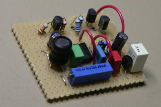
Here is the schematic. It uses
the common MC34063 switch-mode controller to produce a negative
voltage, which is regulated by a 79L06 linear regulator, and the final
ALC voltage is adjusted by a potentiometer. The whole thing is powered
up only when the tuner is actually tuning. I built the thing on a
piece of Veroboard.
|
|
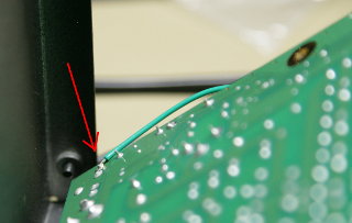
 The tip of the tuner's "Radio Interface" connector (a stereo 3.5 mm
phone jack) is grounded when
the tuner is tuning. This would normally be wired directly to the ring
of the FT-897's ACC connector to enable the tuner to request a carrier
from the radio. I use this signal to activate my own circuit. I
soldered a wire to the underside of the circuit board, to the pins of the
"Radio Interface" jack. The tip
connection is the one closest to the board's
edge.
The tip of the tuner's "Radio Interface" connector (a stereo 3.5 mm
phone jack) is grounded when
the tuner is tuning. This would normally be wired directly to the ring
of the FT-897's ACC connector to enable the tuner to request a carrier
from the radio. I use this signal to activate my own circuit. I
soldered a wire to the underside of the circuit board, to the pins of the
"Radio Interface" jack. The tip
connection is the one closest to the board's
edge.
|

|
I installed the internal batteries as per LDG's own instructions, but
I take the power for my own circuit from the board, at the cathode end
of diode D9,
where power is available also when the batteries are dead and the LDG
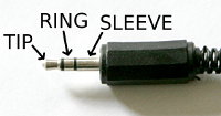
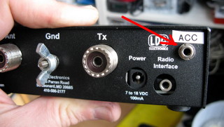
operates on external power. A 3.5 mm stereo jack is added to the back panel of the tuner, with ferrite beads and bypass capacitors added for good measure. The tip is the ALC voltage, the ring is the TX-request signal (grounded to request transmission), and the sleeve is of course ground.
|
|
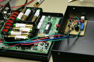
Two 4-AAA battery holders are installed with double-sided tape onto
the top of the relays on the circuit board, as recommended by LDG in
the tuner's manual. My circuit, built on a piece of
Veroboard, is stuck onto the top chassis with double-sided tape. Once installed, the potentiometer is adjusted so that about a watt of power is transmitted during tuning. This is plenty for the LDG's circuits to detect forward and reflected power. I used the power meter on my MFJ-941E VersaTuner II to adjust the power level while transmitting into a 50-ohm dummy load. I also used the VersaTuner to de-tune the dummy load, so I could test the LDG tuner. |
|
With the modification in place, a straight 3.5 mm stereo male-male audio
cable is used to connect the new ACC jack on the tuner
to the radio's ACC connector. Now tuning is a
simple matter: Switch bands, hit Tune on the LDG, and you're
done. Only a watt or so is transmitted during tuning, which creates
less QRM and also less wear on the relay contacts within the
tuner. And it saves battery power when operating portable—which
is how I use this tuner most of the time. The original "Radio Interface" jack still works as before. I don't use it for anything, though. |