<HOME
<Electronics
t.Bone freeU twin HT 823 gain modification
Increase the AF gain of the wireless microphone transmitter to reduce
the background noise
|
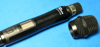
The t.Bone freeU Twin HT 823 is a cheap but quite reasonable
wireless UHF microphone system with two hand microphones with selectable
frequencies and adjustable transmit power, pilot tone (used to unmute the
receiver when a mic is active) and a dual diversity receiver.
This one operates in the 823 MHz band, and there is another system
available for 863 MHz—the information presented here is probably
valid for its hand microphones as well. Bodypack microphone transmitters
are also available for both systems, but I have no experience of those.
The system is quite ok for its price, and the hand microphones have a good
look and feel to them, but the audio volume is extremely low!
The receiver has volume bargraph meters and controls, but the meters show
absolutely nothing unless I really yell into the microphone.
And I can't even imagine why anyone would want to set the volume
controls to anything but absolute maximum.
I inquired from Thomann about this,
but they said it was normal.
Now, I do understand the critical need to have enough headroom in a
wireless system—but the ridiculously low volume of these microphones
caused electrical noise, probably from the microphone's switch-mode
power supply, to be distinctly noticeable in the background,
especially when using any compression! The noise changed character when
transmit power was changed—even at very close distance—so I
knew the problem was in the transmitter, not in the receiver.
Since these microphones would only be used for speaking (not for loud
screaming in a heavy rock band live gig), I very much wanted to increase
the AF gain in the microphones in order to reduce the audibility of the
background noise. But of course, the transmitters had no AF gain adjustment.
So I had to go inside the microphones for a look around, to see if there was
anything I could improve. Unlike the three
different mixers
that I've done various modifications on, these microphones did not offer me
the benefit of a schematic diagram.
|
|
Getting the first microphone open was a lot of guesswork, as it did not
really provide any helpful indication as to how it should be done, and
I did not want to break anything by applying undue violence. But once I
figured it out, there was nothing too difficult about it:
|
First loosen the set screw on the side of the microphone head. It's a
1.5 mm hex (Allen) screw—make sure you use a good quality,
undamaged metric hex key (not an 0.05 inch one) or
you'll round out the screw head and never get it open. (I even placed a
tiny droplet of silicone oil on the thread, and let it seep in before
trying to open the screw, but maybe I'm just overly paranoid.) You just
need to loosen the screw (not remove it completely), then you can unscrew
the entire grille head from the microphone body.
But if you do destroy the screw head, you won't be able to remove the
grille, and that has to come off in order to take the microphone apart.
In the worst case, you'll have to drill out the set screw—good luck
with that!
|
|
Note that it's now possible to wash the head grille and foam interior
if someone has sneezed on it. When reassembling my microphone, I never
bothered to tighten the set screw again—the grille assembly stays
in place even without it, and some day I might actually want to
clean it! I think it's strange that the grille is not intended to be
removable. An AKG Perception P5s wired mic I have actually
explains in its manual how to remove and wash its grille! (It also comes
off by unscrewing it from the mic body, but it has no minuscle set screw
to deal with.)
|
|
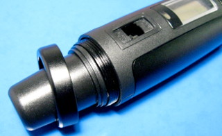
Next unscrew the retainer ring at the bottom end of the microphone body.
This ring is the same diameter as the rest
of the body—don't try to remove the slightly thinner, tapering
end cap just yet. And here's the thing: this ring has a reverse
thread, so you must rotate the ring clockwise as seen from the
bottom end—in the direction you would normally expect to
tighten any threaded part.
This is the bit that took a while to figure out. Everything else was
pretty obvious.
|
|
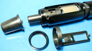
Now pull off the tapering end cap. Next remove the cap from the power
switch—just pry it up from either end with your fingernail, it's not
tight (although replacing it again during reassembly is a bit
fiddly—the hardest part of the whole modification, in fact).
Then remove the plastic part that contains the transparent display
cover (that thing at front right in the photo).
Next open up the microphone by unscrewing it from the center, in the usual
way as if you were removing the batteries. (If you like, you can remove the
batteries, but you may leave them in as well—you'll need them while
testing the microphone later.) At this point, neither half of the aluminum
body can be completely removed yet.
|
|
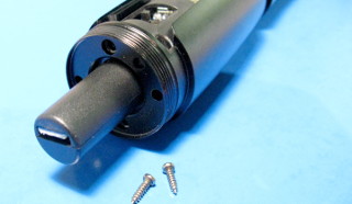
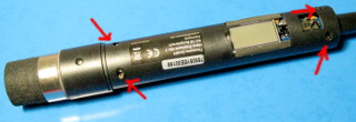
Remove the two screws that are now accessible at the bottom end of the
microphone. Note which holes they are in—there's six holes in
total, two of which are empty (the protrusions on the end cap go in
those), two appear filled, and two are for the screws. With the display
facing up, the screws are at the 12 o'clock and 6 o'clock
positions.
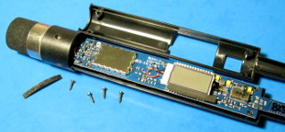
Once you have done this, you can slide off the bottom half of the
microphone's aluminum shell. It will only just clear the power
switch, so be careful there. Then slide off the top half of the shell
as well, downwards along the body (this is why the grille had to
come off) and, again, be careful of the power switch.
|
|
Now you are left with just the plastic interior body of the microphone.
On the side with the display, there are four recessed screws immediately
obvious. Unscrew these, and try to lift off the top half of the plastic
cover. There's two rubbery bits along the sides of the display, which are
stuck on like adhesive tape. Depending on how they're positioned, you may
need to remove one or both of these first, before you can get the cover off.
I think their only purpose is to reduce the glare of the display backlight.
Try not to touch their adhesive side with your fingers too much, or get
dust on them, or let them stick to anything untoward, as you'll want to
stick them back on later. A piece of non-stick baking parchment from your
kitchen might be a safe surface to store these on.
|
|
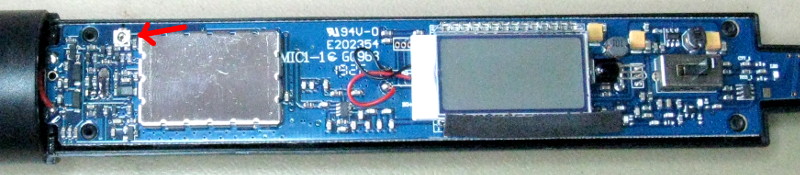
The circuit board is now exposed for your perusal. Mine contains markings
"94V-0 E202354 MIC1-1 GQ968 1926", in case that means anything.
(I could not find a schematic with these search terms. I did try, of
course, because that's how I found the schematic for my
t.Mix MIX 802 mixer, based on the markings
on its PCB.)
Note that in this state
the microphone is still functionally intact, so testing is easy without
any need for reassembly. The batteries stay in place nicely, the power
switch is easily accessible, and the missing grille won't really affect
the volume too much to matter.
|
The back side of the board is obscured by the lower half of the plastic
cover, and the battery contacts that extend through the plastic part would
probably make it a pain to remove, so I didn't try. However,
the front side has several components that are easy to identify.
Firstly, there's the antenna, which is etched right onto the board. (I
wonder if an SMA connector could be fitted there in order to use an external
antenna to increase range? That modification might be illegal, though,
this being a license-free radio transmitter. Those typically have limits
on their effective radiated power, and substituting a more efficient antenna
might breach those limits.) Nearby
is the power switch, and close to it are two inductors, three
orange-yellow tantalum capacitors, and some controller IC, which likely
comprise a switch-mode power supply. Then there's the display, and
a large metal can which likely contains the RF modulator. Between it and
the microphone capsule, there's a mess of passive components and some
8-legged IC on the back side of the board—I'd be surprised if that
weren't an op-amp. And then there's a single trimmer potentiometer
nearby... I cannot imagine that potentiometer serving any other purpose
than to adjust audio gain.
* UPDATE * Ronald Meyvisch informed me that his HT 823
had a different circuit board, and the audio gain potentiometer was inside the
RF shielding metal can. Its lid can be pried off with a screwdriver. (I'm
actually not surprised that there are multiple versions of the PCB for the
same product.) Thanks to Ronald for the info!

|
Before I got down to probing the potentiometer with an oscilloscope,
I checked the mic's
radio signal with my spectrum analyzer. My
intention was to check the sidebands with no input audio (i.e.
pilot tone only) before and after modification, to see how much the
pilot tone was affected by the modification.
This
is what it looked like before. It was not that different after, either.
Once I got to work with the oscilloscope, of course, I found the pilot
tone itself and could measure it directly. I just wanted to show you
the spectrum, though, because it's so cool. :)
|
|
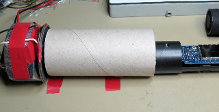
I jerry rigged a
standard sound source out
of a signal generator, a small speaker held vertical by a huge
handicraft nut, and a TP tube. While feeding
the mic with this constant audio, I probed the potentiometer with an
oscilloscope. Sure enough, it seemed to be passing baseband audio,
overlaid with a 32 kHz signal, which is probably the pilot tone. So I
tried adjusting it with a non-conductive ceramic screw driver (of course,
I first marked its original position with a sharp felt-tip marker). Turning
it counter-clockwise increased audio gain, but also decreased the amplitude
of the 32 kHz pilot tone. That shouldn't matter as long as the receiver
detects it properly, which it did even when I turned the pot all the way
to the end.
I adjusted the gain for a suitable dynamic range while speaking into the
mic, using the receiver's bargraph as an indicator. Then I adjusted the
other microphone to the same gain, using my standard sound source and
monitoring the receiver's output on an oscilloscope. In both mics, the pot
ended up almost 90° counter-clockwise from its original position.
|
The modification improved the microphones quite a bit, though some
SMPS noise still remains if I really crank up the gain in my mixer. Hey,
the system was dirt cheap! Now, after modification, I'd rate its
performance on par with its price. A couple of segments flicker on the
receiver's bargraph when I talk into the mic, and if I really yell,
I can just max it out. Should do for speaking perfectly.
There was nothing too difficult about this modification (other than getting
the microphone open the first time), and if you don't get into extensive
measurements with oscilloscopes etc, you could conceivably modify both mics
in an hour. But do realize, that if you manage to damage something inside,
you'll have a broken microphone, congratulations!
So don't attempt this modification unless you know what you are doing
and are willing to take that risk, and in any case don't blame me for
anything bad that happens!
Antti J. Niskanen <uuki@iki.fi>